

Cleaning device
- Summary
- Abstract
- Description
- Claims
- Application Information
AI Technical Summary
Benefits of technology
Problems solved by technology
Method used
Image

Examples
Embodiment Construction
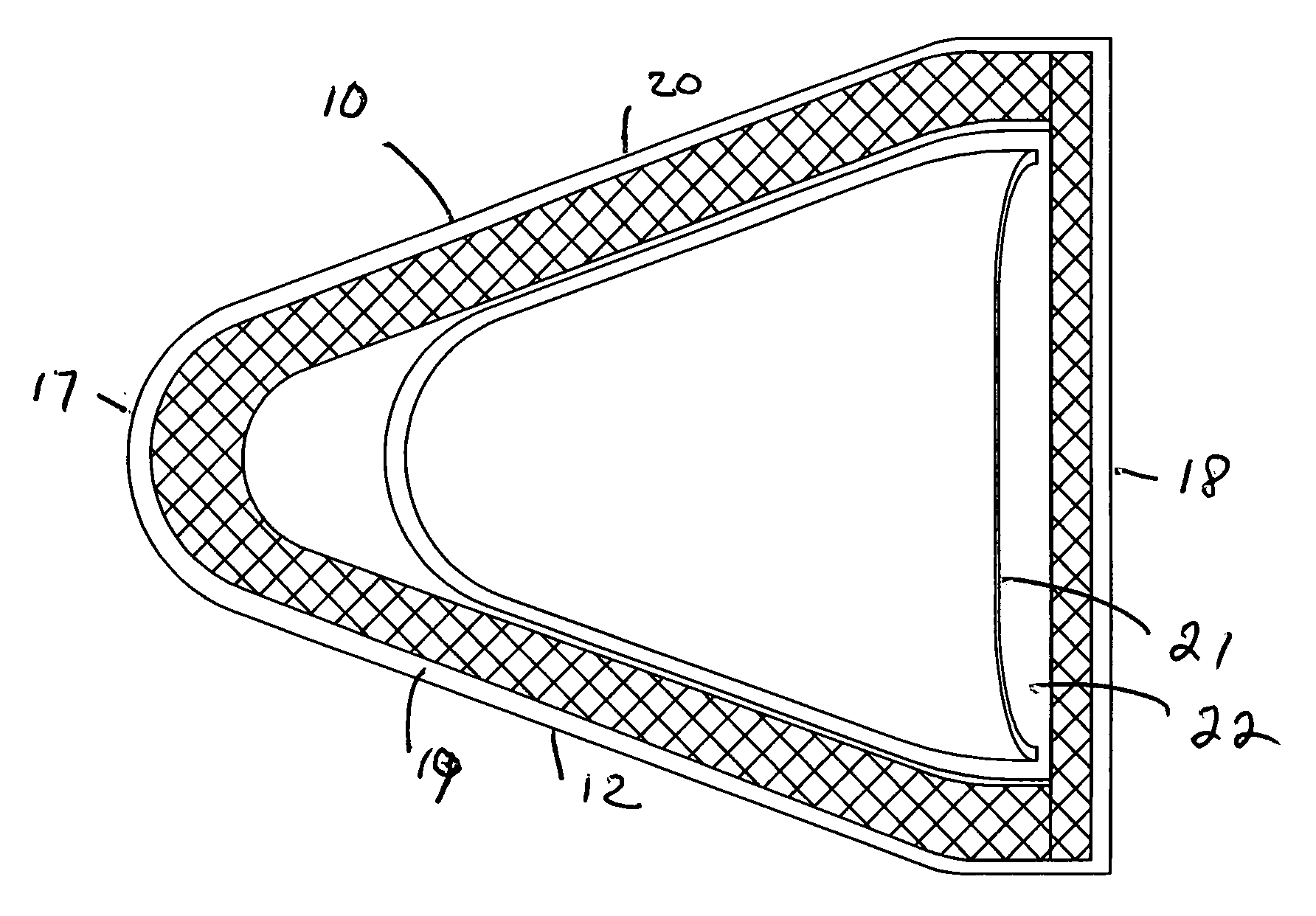
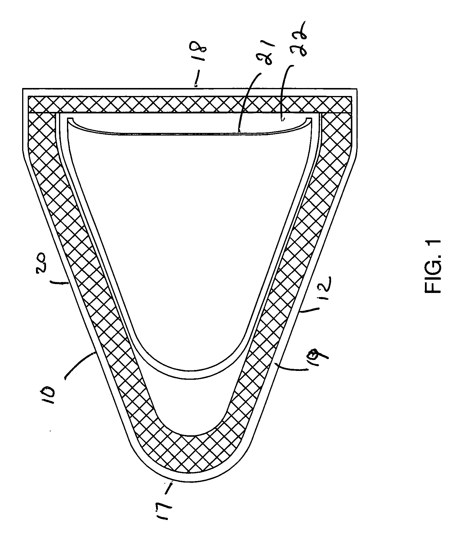
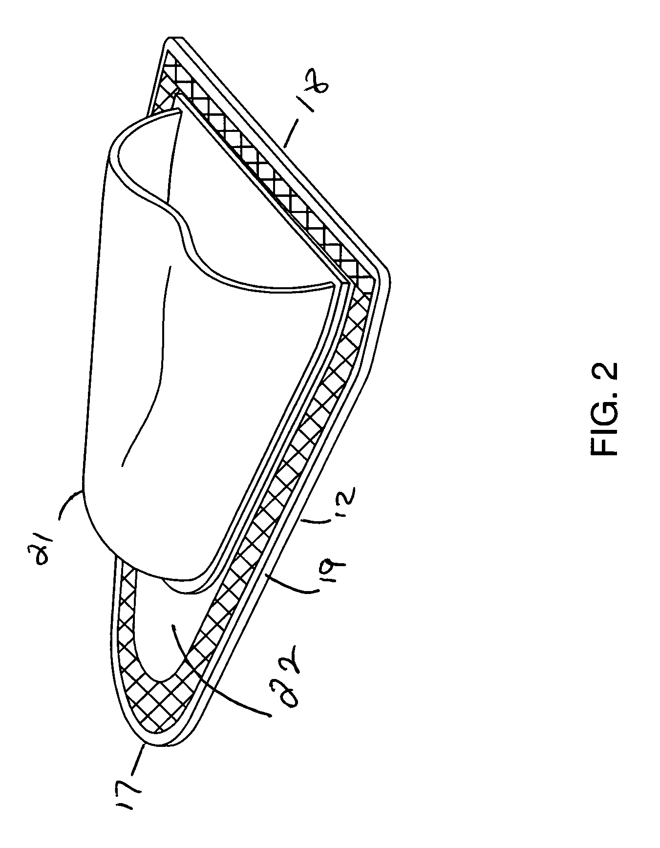
[0023]Applicant's invention can clean the inside and outside window at the same time, save time and work, by means of ultra strong magnets. In a preferred embodiment there is a first housing 10 with at least one magnet and a second housing 30 with a material that is attracted to a magnet or a magnetic member.
[0024]In a preferred embodiment as seen in FIG. 7 there is a base layer 11 which is comprised of an outer surface 12 and an inner surface 13. The outer surface 12 contacts a glass or other material to be cleaned. The base layer is preferably a micro fiber material. A second layer is made up of a flexible magnetic sheet 14. The flexible magnetic sheet may be of any suitable magnetic strength. Preferably, the magnetic sheet should be as strong as possible. One preferred magnetic sheet is a magnetic sheet sold by Rochester Magnet of East Rochester, N.Y. This flexible magnet withstands cracking at 68° F. while wrapped around a 0.5″ diameter rod. Other flexible magnets are also suita...
PUM
 Abstract
Description
Claims
Application Information