Suction device for cleaning a nozzle surface of a print head

a technology for cleaning nozzles and print heads, which is applied in printing and other directions, can solve the problems of increasing the cost of suction devices, introducing errors, and the area on the surface of the nozzle surface on which the spacers are supported cannot be effectively cleaned by suction devices, so as to achieve effective cleaning of the surface and mitigate the above mentioned drawbacks

Inactive Publication Date: 2015-04-21
OCE TECH
View PDF3 Cites 0 Cited by
  • Summary
  • Abstract
  • Description
  • Claims
  • Application Information

AI Technical Summary

Benefits of technology

[0009]It is accordingly an object of the present invention to provide a suction device for effectively cleaning the surface of a nozzle surface of a print head, which suction device mitigates the above mentioned drawbacks.

Problems solved by technology

However the use of an external positioning element increases the cost of the suction device and may introduce errors into the height, the x-rotation and y-rotation between the aligned nozzle surface and the suction surface.
A drawback of using spacers which are supported on the nozzle surface is that the area on the surface of the nozzle surface on which the spacers are supported cannot effectively be cleaned by the suction device.
As a result dirt and ink which remain on these areas of the nozzle surface may reduce the reliability of jetting inkjet droplets from the print head.

Method used


Image

  • Suction device for cleaning a nozzle surface of a print head
  • Suction device for cleaning a nozzle surface of a print head
  • Suction device for cleaning a nozzle surface of a print head

Examples


first embodiment

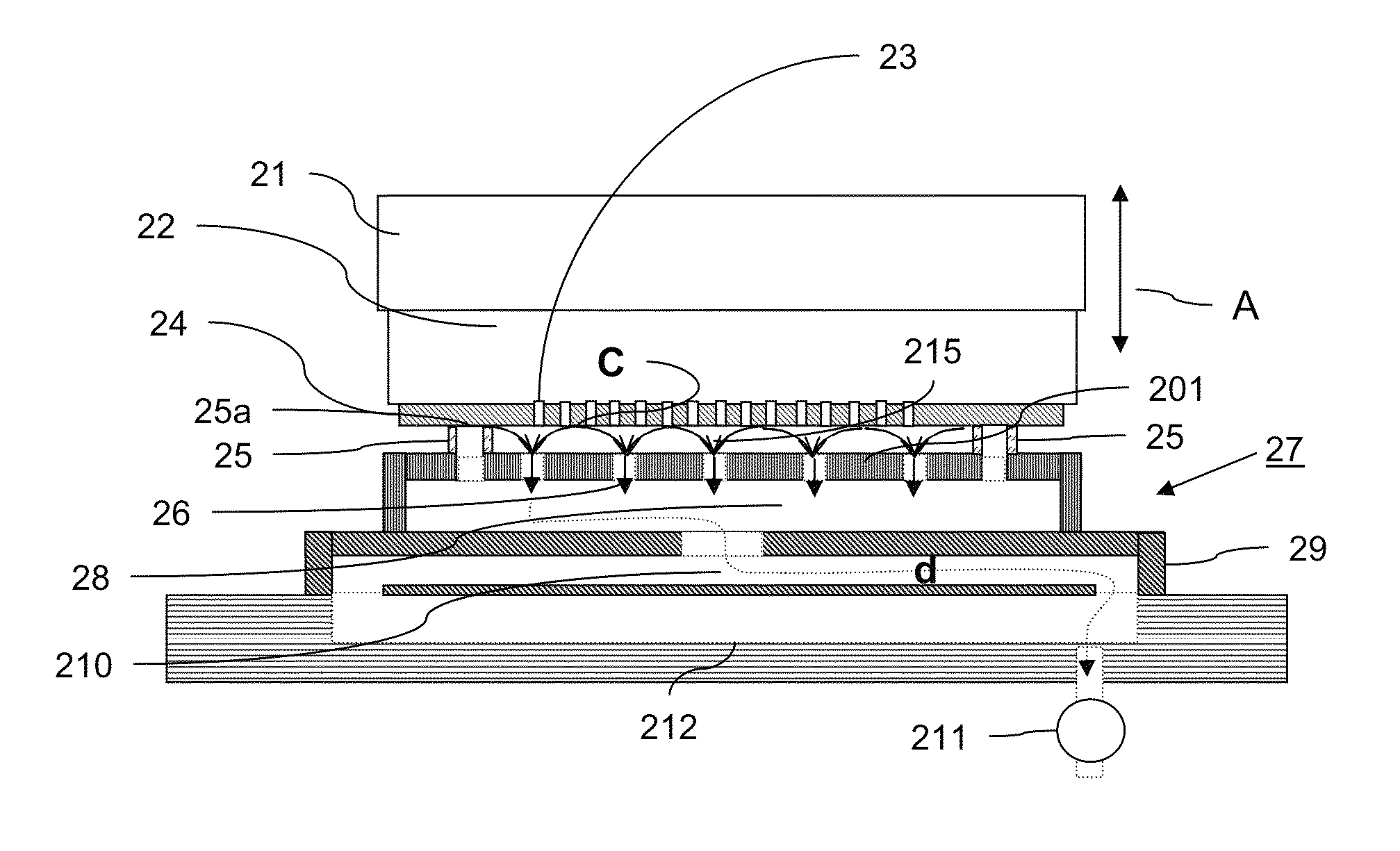
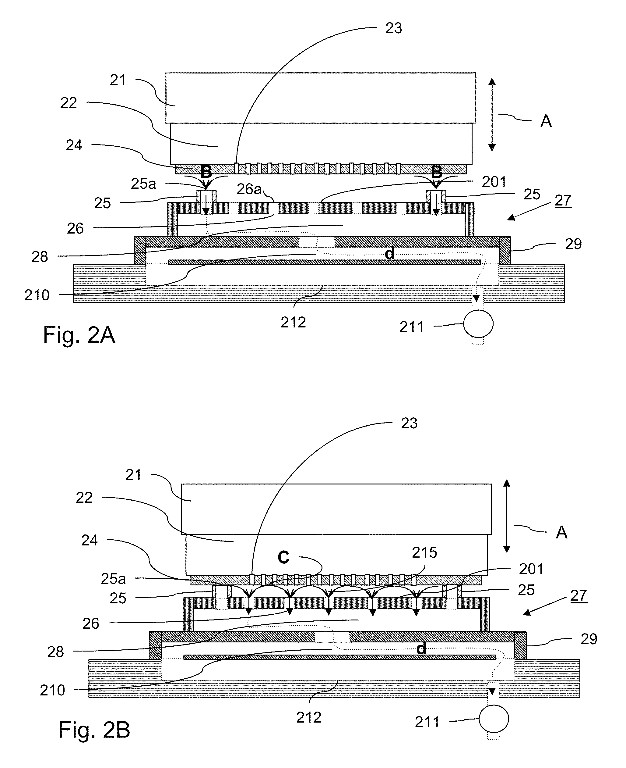
[0075]FIGS. 2A and 2B show a suction device according to the present invention. Suction device 27 is positioned close to print head 22. Print head 22 comprises nozzle surface 24, which comprises a plurality of nozzles 23. Each nozzle is connected to a print head ink chamber (not shown). The print head 22 is mounted on carriage 21. The print head 22 and the carriage 21 may be moved in z-direction (indicated by arrow A), which is perpendicular to a direction (x and y-direction) of the nozzle surface 24.

[0076]Suction device 27 comprises a suction surface 201, which comprises a plurality of suction openings 26a, each being operatively coupled to a suction channel 26, which suction openings 26a are arranged in a row. Two spacers 25 are arranged on top of one of the suction channels at both ends of the row of suction channels. Each spacer 25 comprises a spacer opening 25a, which is operatively coupled to a spacer channel 25b being operatively coupled to the suction channel beneath the hol...

second embodiment

[0085]FIG. 3 shows a suction device according to the present invention. Suction device 37 is positioned close to print head 22.

[0086]Suction device 37 comprises a suction surface 301, which comprises a plurality of suction openings 36a operatively coupled to suction channels 36, which are arranged in a row. Two spacers 35 are arranged near both ends of the row of suction channels 36. Each spacer 35 comprises a spacer opening 35a, which is operatively coupled to an air flow chamber 313 beneath the spacer opening. The two spacers are sized to position the suction surface 301 at a predetermined height above the nozzle surface to be cleaned. The air flow chambers 313 are operatively coupled to an external air flow source (not shown). The buffer 38, which is operatively coupled to the suction channels 26, is slightly smaller. The other parts of the suction device 37 are similar to the parts of the suction device 27.

[0087]FIG. 3 shows the suction device 37 in case the spacers 35 are posit...


PUM


Abstract

A suction device is provided for cleaning a nozzle surface of a print head. The suction device comprises a suction surface and a spacer, whereby the spacer is provided with a spacer channel, the spacer channel comprising a spacer opening at an outer surface of the spacer and the spacer channel being operatively coupled to an air flow source. The spacer is configured for positioning the suction surface at a predetermined distance from the nozzle surface for providing a suction gap. The suction device is configured to provide in operation an air flow through the suction gap, along the nozzle surface and into the suction channel. An air flow may be provided through the spacer channel of the spacer in order to clean an area of the nozzle surface of the print head.

Description

CROSS REFERENCE TO RELATED APPLICATIONS[0001]This non-provisional application is a Continuation of International Application No. PCT / EP2012 / 062985 filed on Jul. 4, 2012, which claims priority under 35 U.S.C. 119(e) to U.S. Provisional Application No. 61 / 509,387 filed on Jul. 19, 2011 and under 35 U.S.C. 119(a) to European Patent Application No. 11174796.0 filed in Europe on Jul. 21, 2011, all of which are hereby expressly incorporated by reference into the present application.FIELD OF THE INVENTION[0002]The present invention relates to a suction device for cleaning a nozzle surface of a print head. The present invention further relates to a method for cleaning a nozzle surface of a print head by using the suction device.BACKGROUND OF THE INVENTION[0003]A suction device is commonly used for cleaning a nozzle surface of a print head. In case dirt on the nozzle surface of the print head or air bubbles in the ink chambers of the print head inhibits the accurate and reliable jetting of i...

Claims


Application Information

Patent Timeline
Patent Type & Authority Patents(United States)
IPC IPC(8): B41J2/165
CPCB41J2/16523B41J2/16511B41J2/1652B41J2/16532
Inventor ELFERINK, MAARTEN J. H.
Owner OCE TECH
Why Eureka
Try Eureka