Van Wheel of Turbine Comprising a Vane and at Least One Cooling Channel

a technology of turbines and vanes, which is applied in the direction of liquid fuel engines, vessel construction, marine propulsion, etc., to achieve the effect of improving the efficiency of gas turbines and increasing the useful life of vanes

Active Publication Date: 2008-10-30
SIEMENS ENERGY GLOBAL GMBH & CO KG
View PDF11 Cites 10 Cited by
  • Summary
  • Abstract
  • Description
  • Claims
  • Application Information

AI Technical Summary

Benefits of technology

[0005]An object on which the invention is based is to provide a vane wheel for a turbine comprising a vane, at the vane foot or vane platform of which reinforced cooling can be achieved and a comparatively high heat flow can be discharged. Furthermore, the object of the invention is to specify a production method for such a vane. This first-mentioned object is achieved, according to the invention, in that, on at least one of the walls of the cooling channel of a vane wheel according to the invention, a multiplicity of turbulators are formed, which are configured in such a way that they increase the turbulence of a cooling fluid flowing through the cooling channel.
[0008]In an advantageous development of the vane wheel according to the invention, the multiplicity of turbulators are advantageously formed on the underside of a platform of the vane foot. By the use of turbulators or turbulence elements on the platform underside, which increase the turbulence in the gap between the vane foot and the disk head of the wheel disk, the heat flow in the platform wall is increased and the platform surface temperature is lowered.
[0012]Furthermore, in the vane wheel according to the invention, the vane foot of at least one vane should advantageously be configured with a platform, on which a cooling channel is located on each of the two sides along an elongated neck of the vane foot, and the multiplicity of turbulators should be configured in the form of a row extending in the associated cooling channel on the underside of the platform. By means of such turbulators on the underside of the platform, vanes of vane wheels according to the invention can be made capable of use at higher temperatures without major structural modification.
[0015]The object of the invention is achieved, furthermore, by means of a vane for a vane wheel of a turbine, in particular a gas turbine, which is provided with a vane leaf around which a hot gas can flow and with a vane foot having a platform which, with respect to the main flow direction of the hot gas, extends from an inflow-side edge to an outflow-side edge along a longitudinal platform edge, and in which, on the underside, facing away from the vane leaf, of the platform, along the longitudinal platform edge, a multiplicity of turbulators are formed, which are configured in such a way that, in the built-in state of the vane, they increase the turbulence of a cooling fluid flowing along the underside.
[0016]As explained above, on such a vane according to the invention, improved heat discharge and cooling are achieved in the region of the associated vane foot, thus resulting, virtually without any cost outlay, in an increased sale value of the machines.
[0019]Alternatively, an already existing vane which is being used can be retrofitted with the turbulators during an inspection interval of the gas turbine, in that these are shaped in a separate operation after at least one operation forming the vane leaf. As a result, the useful life of the vane can be further increased, while at the same time cooling air is saved, this, furthermore, having a positive effect on the efficiency of the gas turbine.

Problems solved by technology

The cooling of the vane leaves and, in particular, of the vane feet of such gas turbine vanes subjected to high temperature loads is particularly involved because of the complicated cooling fluid routing required for this purpose and the difficult sealing-off work, along with the high centrifugal force load.
Often, only a comparatively small quantity of cooling fluid is available, so that only a low heat flow can be discharged through a platform of the vane foot.

Method used


Image

  • Van Wheel of Turbine Comprising a Vane and at Least One Cooling Channel
  • Van Wheel of Turbine Comprising a Vane and at Least One Cooling Channel
  • Van Wheel of Turbine Comprising a Vane and at Least One Cooling Channel

Examples


Embodiment Construction

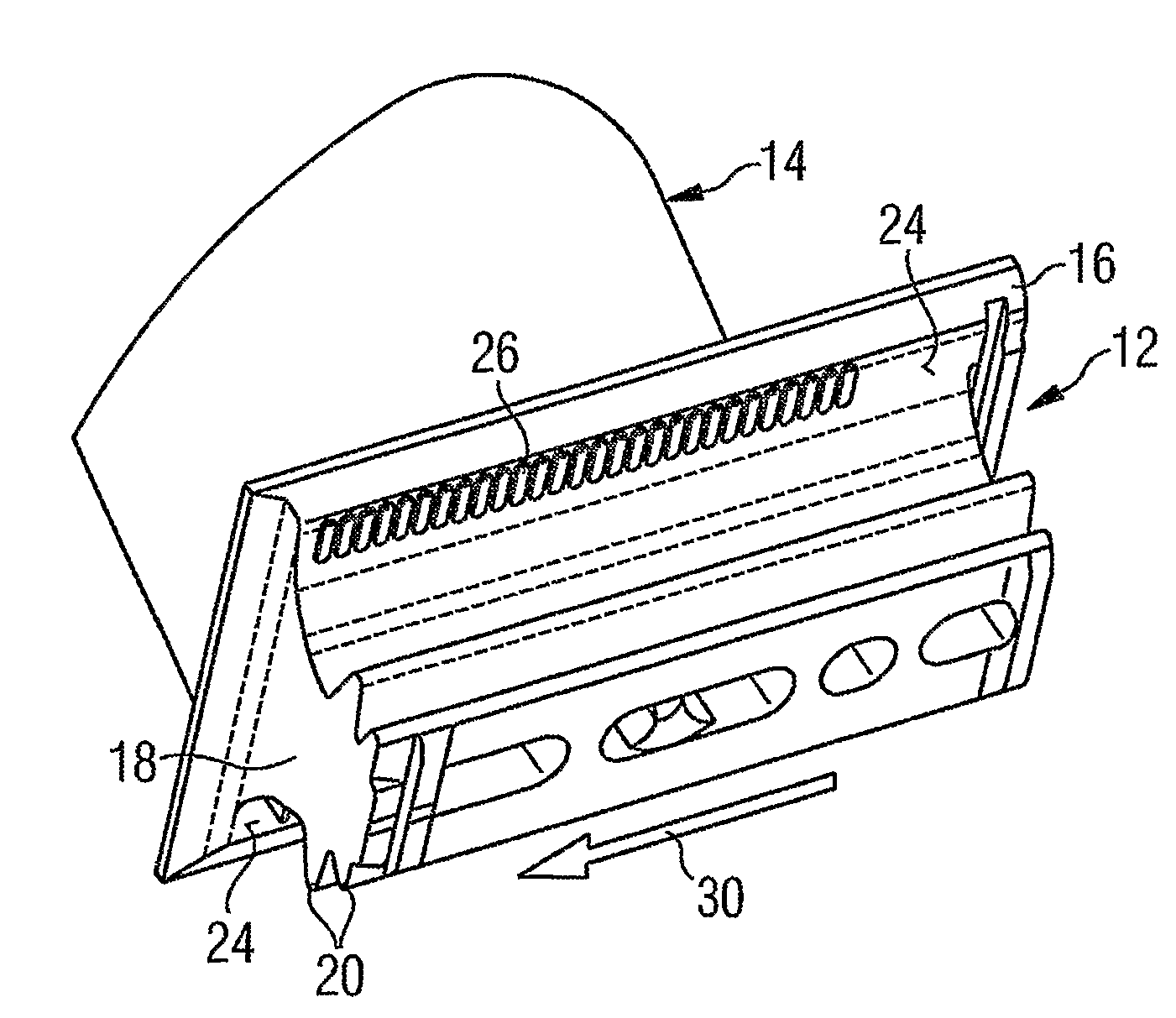
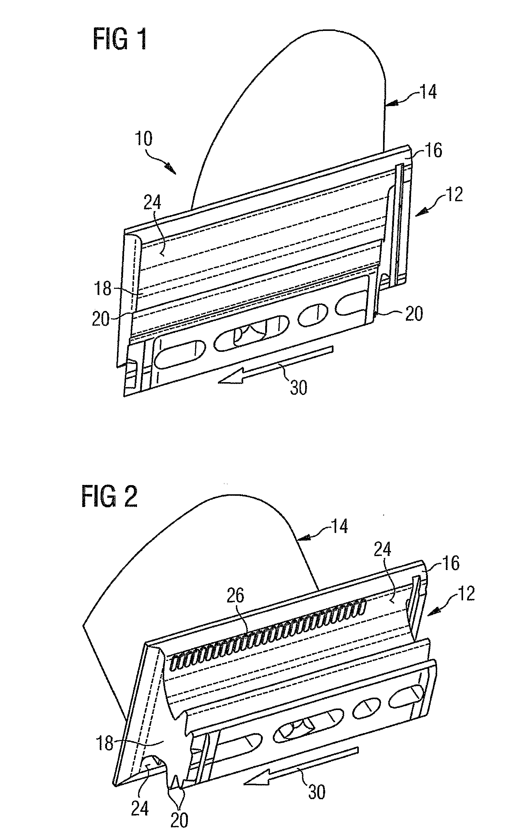
[0024]FIG. 1 illustrates a vane 10 according to the prior art which has a vane foot 12 and a vane leaf 14 adjoining the latter. The vane foot 12 is configured as a pinetree foot with a platform 16, on which a neck 18 is arranged on the side lying opposite the vane leaf 14 and, further away, teeth 20 are arranged. The platform 16, the neck 18 and the teeth 20 are configured as an elongate profile which, with the vane 10 built in, is arranged in a groove, not illustrated, of a wheel disk 22 of the turbine rotor and is provided there for holding the vane leaf 14 and for the absorption of, in particular, centrifugal forces of the latter.

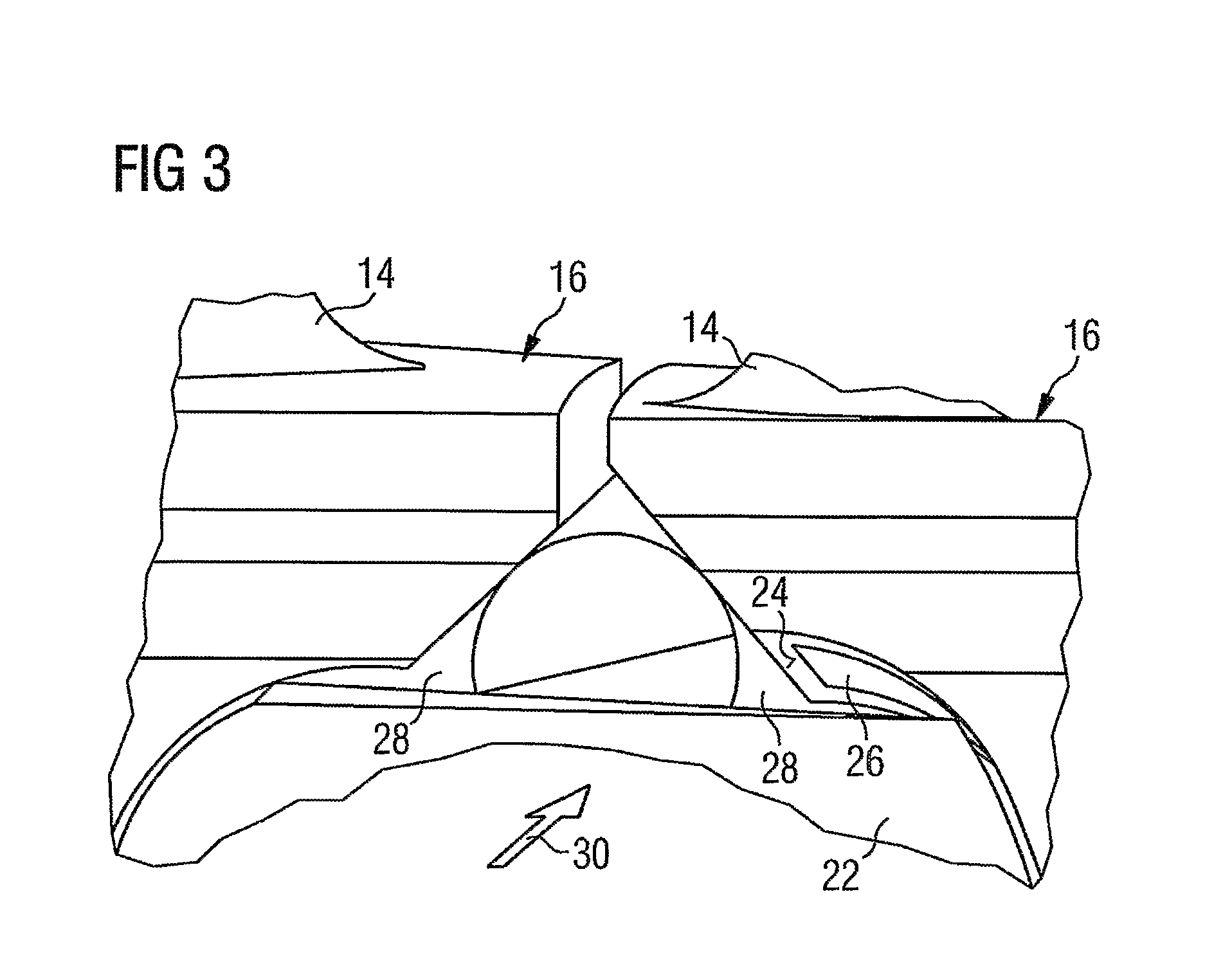
[0025]Such a built-in position of a vane 10 on a wheel disk 22 is basically illustrated in FIG. 3.

[0026]As can be seen in FIG. 1, in the known vane 10, the underside, facing the neck 18 and the teeth 20, of the platform 16 is provided with an essentially smooth surface.

[0027]In the case of a vane 10, illustrated in FIG. 2, which is configured basically i...


PUM


Abstract

There is described a vane wheel of a turbine comprising at least one vane, the footing thereof being held on a wheel disk. At least one cooling channel is arranged between the wheel disk and the vane footing. Said vane wheel having a plurality of turbulators is embodied on at least one of the walls of the cooling channel, said turbulators being configured in such a way that the turbulence and thus the heat transfer of a cooling fluid flowing through the cooling channel are increased.

Description

CROSS REFERENCE TO RELATED APPLICATIONS[0001]This application is the US National Stage of International Application No. PCT / EP2005 / 052714, filed Jun. 13, 2005 and claims the benefit thereof. The International Application claims the benefits of European application No. 04016237 EP filed Jul. 9, 2004, all of the applications are incorporated by reference herein in their entirety.FIELD OF INVENTION[0002]The invention relates to a vane wheel of a turbine comprising a vane, the vane foot of which is held on a wheel disk, and in which at least one cooling channel is located between the wheel disk of the turbine and the vane foot. The invention relates, furthermore, to a vane of a vane wheel of this type.BACKGROUND OF INVENTION[0003]Vane wheels of the type initially mentioned are used, for example, in stationary gas turbines as moving vane wheels which are arranged downstream of a combustion chamber of the gas turbine in the direction of flow of fuel gas and are exposed to high temperature...

Claims


Application Information

Patent Timeline
Patent Type & Authority Applications(United States)
IPC IPC(8): F01D5/18F01D5/08F01D5/30F01D25/12
CPCF01D5/081F01D5/30F01D25/12F05D2250/291F05D2260/2212F05D2260/22141F05D2230/12F05D2240/127F05D2240/81
Inventor BOLMS, HAN-THOMASHESELHAUS, ANDREASHABEL, ROLANDKOCH, TORSTENMUSGEN, RALF
Owner SIEMENS ENERGY GLOBAL GMBH & CO KG
Why Eureka
Try Eureka