Projection zoom lens

a technology of projection zoom and lens, applied in the field of projection zoom, can solve problems such as not being disclosed, and achieve the effects of eliminating aberrations, improving projection image quality, and easy manufacturing and machining of lenses

Active Publication Date: 2008-11-20
ASIA OPTICAL INT LTD
View PDF3 Cites 20 Cited by
  • Summary
  • Abstract
  • Description
  • Claims
  • Application Information

AI Technical Summary

Benefits of technology

[0014]In comparison with the prior art, the projection zoom lens according to the present invention comprises five lens groups and when the projection zoom lens is zoomed from the wide-angle end to the telephoto end, the second, third and fourth lens groups are moved along the optical axis while the first and fifth lens groups are kept stationary. The projection zoom lens of the present invention is required to satisfy several conditions for effectively eliminating aberrations and improvin

Problems solved by technology

However, this patent only provides the condition between some lens elements of the first and sec

Method used


Image

  • Projection zoom lens
  • Projection zoom lens
  • Projection zoom lens

Examples


Embodiment Construction

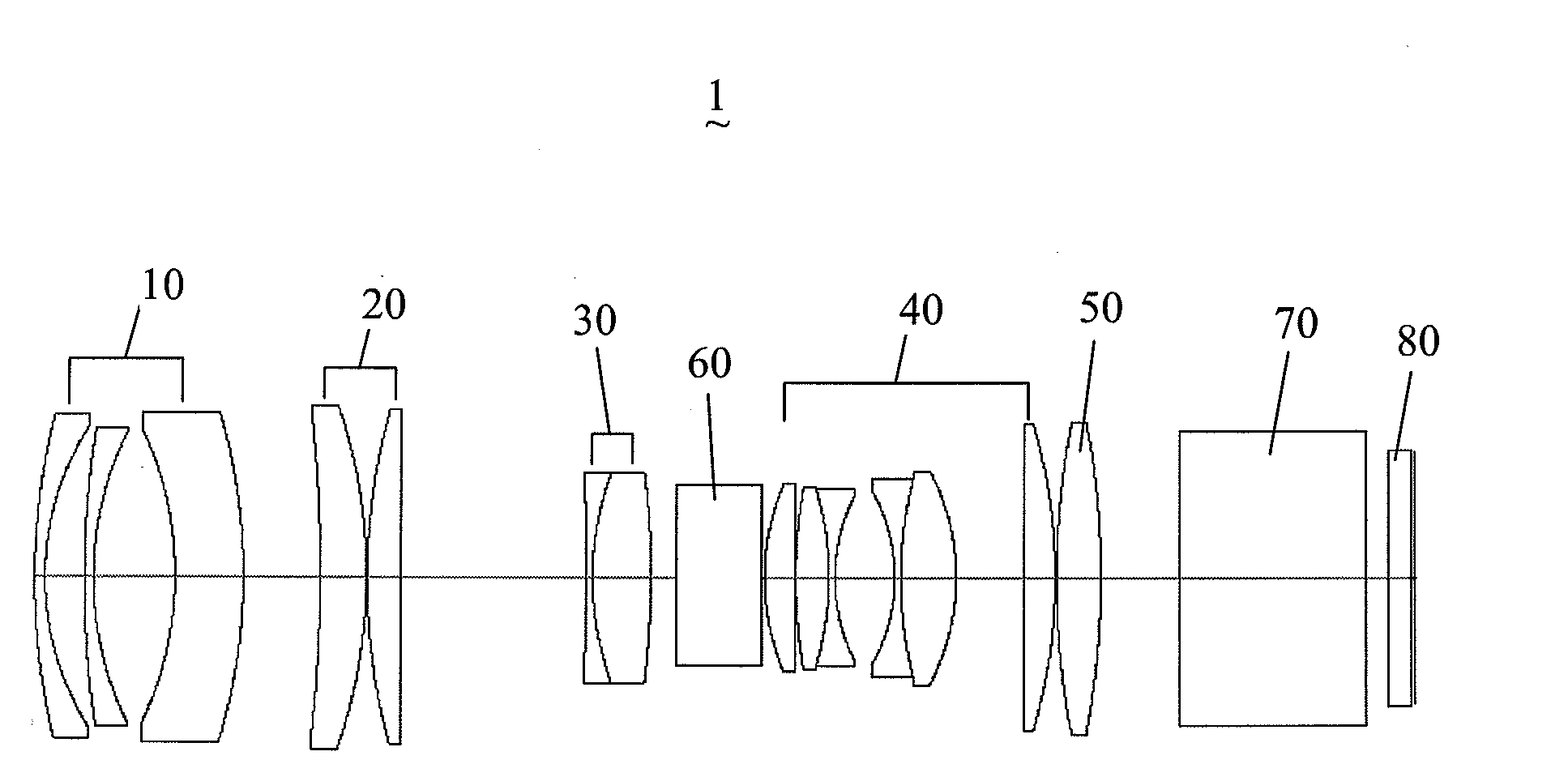
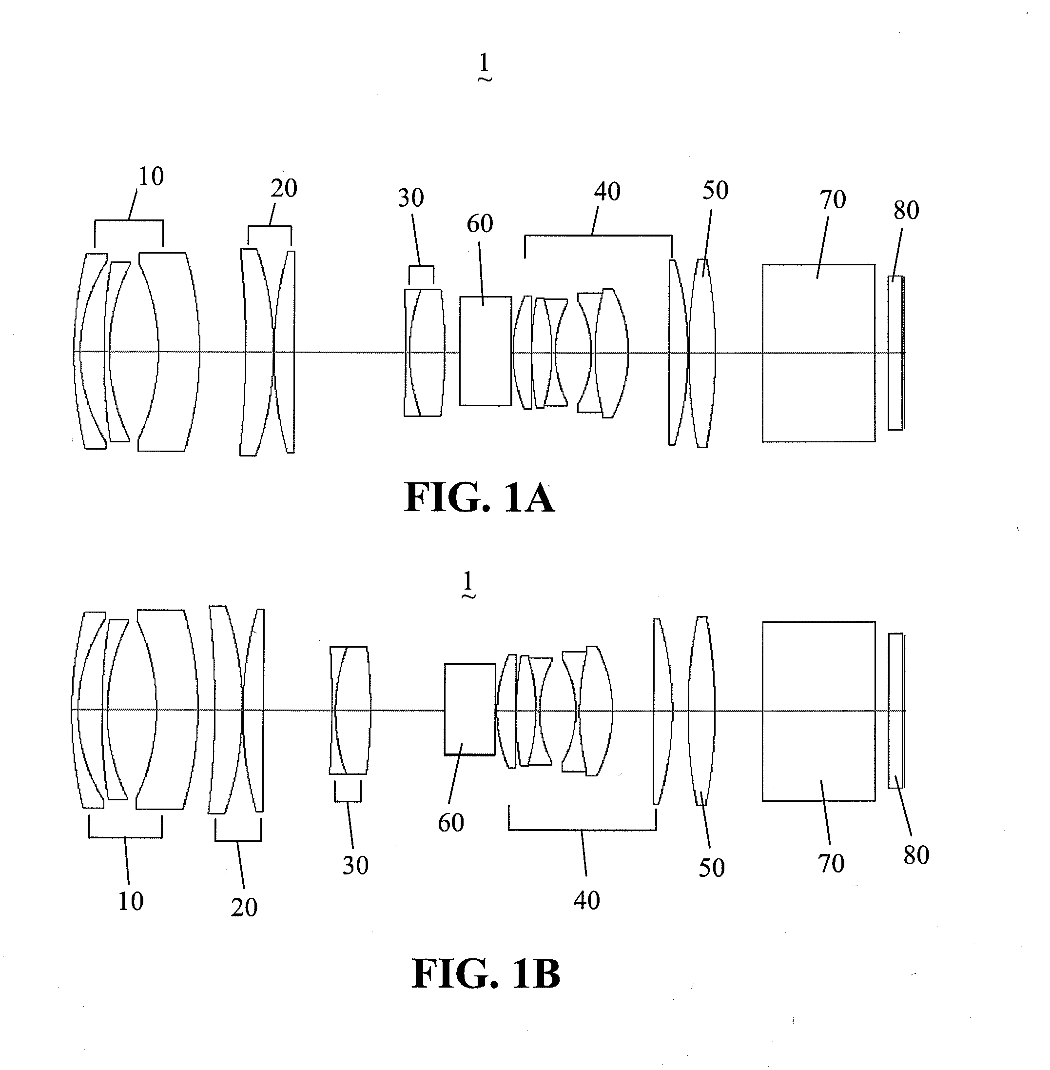
[0020]With reference to the drawings and in particular to FIGS. 1A and 1B, which respectively show the lens construction of a projection zoom lens in accordance with the present invention, generally designated at 1, at a wide-angle end and a telephoto end. The projection zoom lens 1 of the present invention is applicable to a front projector having a telecentric optical system, of which an example is a digital light processing (DLP) projector, for projecting an original image generated or formed by a DMD modulator, which serves as an image source side (the right side as viewed in FIG. 1A) to a large screen which serves as a screen side (the left side as viewed in FIG. 1A).

[0021]The present projection zoom lens 1, which is used to project an original or source image from the image source side to a screen side to form a projected image, comprises, in order from the screen side to the image source side, a first lens group 10 having a negative refractive power, a second lens group 20 ha...


PUM


Abstract

A projection zoom lens includes, from a screen side to an image source side, a first lens group having a negative refractive power, a second lens group having a positive refractive power, a third lens group having a positive refractive power, a fourth lens group having a negative refractive power and a fifth lens group having a positive refractive power. Zooming the projection zoom lens from the wide-angle end to the telephoto end causes the second, third and fourth lens groups to move toward the screen side, and the first and fifth lens groups are kept stationary. The projection zoom lens may further include an auto iris being axially movable with the fourth lens group, a composite prism and a cover glass. The projection zoom lens satisfies several conditions so that it can effectively eliminate aberrations and improve the projection image quality.

Description

BACKGROUND OF THE INVENTION[0001]1. Field of the Invention[0002]The present invention relates to a projection zoom lens, and more particularly to a projection zoom lens for use in a projection optical system of a projector and also for an image-taking optical system of an image-taking device.[0003]2. Description of the Prior Art[0004]Projectors have been widely used in many applications among which the most important application is compact-sized image-related devices. For example, a projector connected to a portable computer or a desktop computer can satisfy many specific requirements of different environments. A commonly known projector, such as a DLP (Digital Light Processing) projector, uses a digital micro-mirror device (DMD) modulator as a light valve, wherein minute mirror-surface elements (micro-mirrors) are arranged in an array corresponding to pixels and form an image by controlling the angles of the respective mirror-surfaces, and a projection zoom lens enlarges and displa...

Claims


Application Information

Patent Timeline
IPC IPC(8): G02B9/60
CPCG02B15/177G02B15/145523
Inventor KUO, CHUNG-YUAN
Owner ASIA OPTICAL INT LTD
Why Eureka
Try Eureka