Arch support with a patterned surface

Inactive Publication Date: 2008-12-25
BODY TECH LAB
View PDF24 Cites 15 Cited by
  • Summary
  • Abstract
  • Description
  • Claims
  • Application Information

AI Technical Summary

Benefits of technology

[0014]Another object of the present invention is to provide an arch support orthotic device that is washable and reusable.
[0015]Another object of the present invention is to provide an arch support orthotic device that does not slip within the shoes in spite of the size of the arch support orthotic device being less than 100% of the shoes.
[0016]To achieve these and other advantages and in accordance with the purpose of the present invention, as embodied and broadly described, the arch support with square or honeycomb structure includes an upper surface facing a wearer's foot, and a lower surface facing the inner sole of the footwear, wherein the upper surface is formed of a deformable semi-rigid material responding flexibly to the weight of the wearer, and wherein the lower surface comprises an arch support section facing the inner sole surface of the footwear including a plurality of support structures that performs an arch supp

Problems solved by technology

Also, since the orthotic must also be light enough in weight to be comfortable to the wearer, merely increasing the thickness of the orthotic device in the arch region does not solve the problem because merely increasing the thi

Method used


Image

  • Arch support with a patterned surface
  • Arch support with a patterned surface
  • Arch support with a patterned surface

Examples


first embodiment

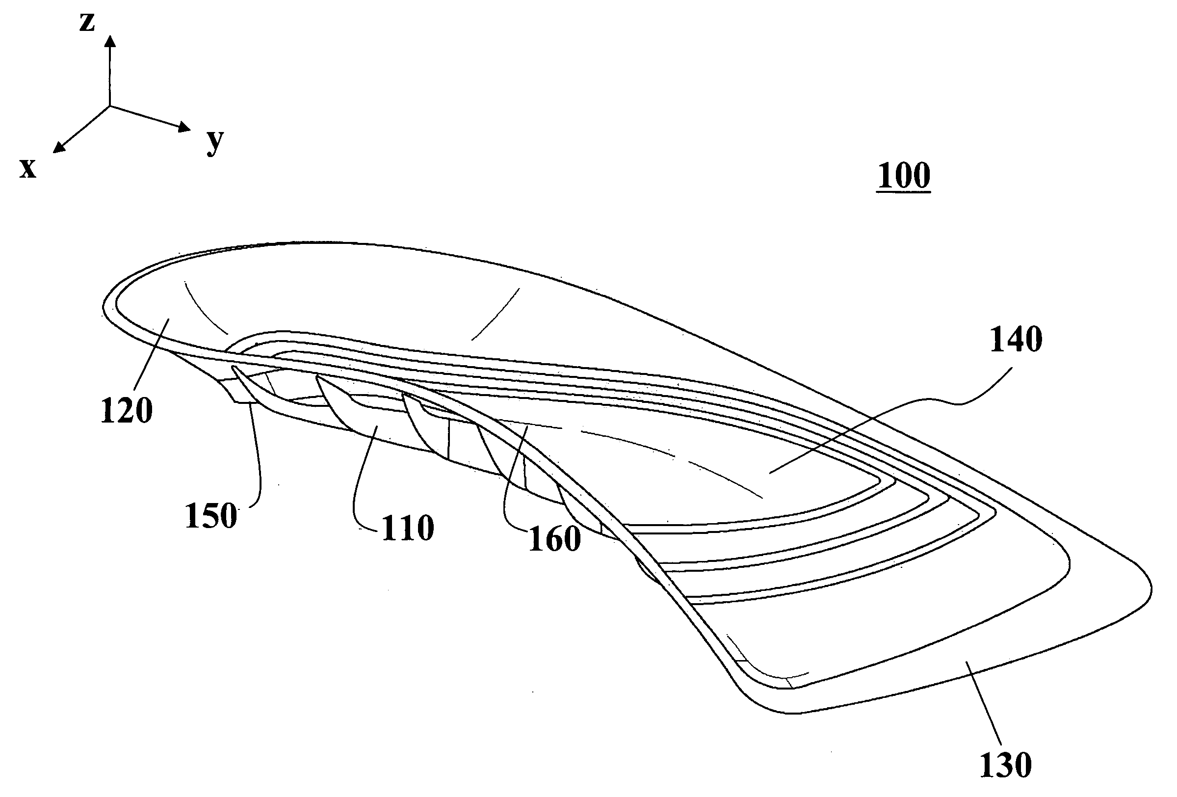
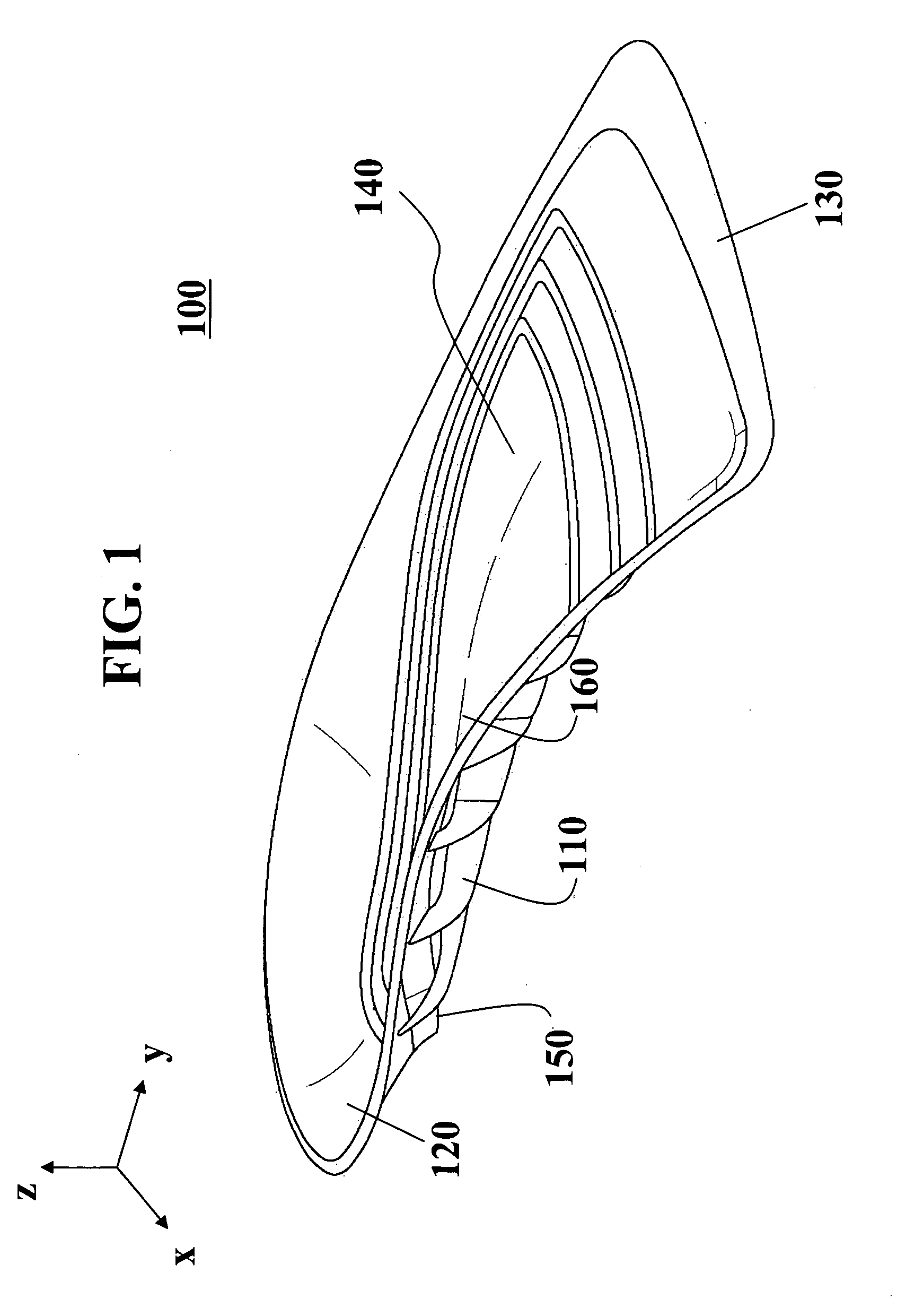
[0035]FIG. 1 is a perspective view of an exemplary arch support orthotic device including a plurality of square support structures according to the present invention. In FIG. 1, the arch support orthotic device 100 comprises a proximal end (heel region) 120, distal end (toe region) 130, an upper surface 140 facing a wearer's foot and a lower surface 150 facing an inner sole surface of a footwear.

[0036]The upper surface 140 of the arch support orthotic device 100 is formed of a deformable semi-rigid material, such as polyethylene, polypropylene, nylon, subortholon or the like, adequate to provide arch support for the expected wearer. The upper surface 140 is contoured to conform generally to the arch of a foot in the manner well-known in the art.

[0037]The lower surface 150 of the arch support orthotic device 100 includes interconnected arch support structures 110. In this exemplary embodiment, the arch support structures 110 are formed of a plurality of substantially square structure...

second embodiment

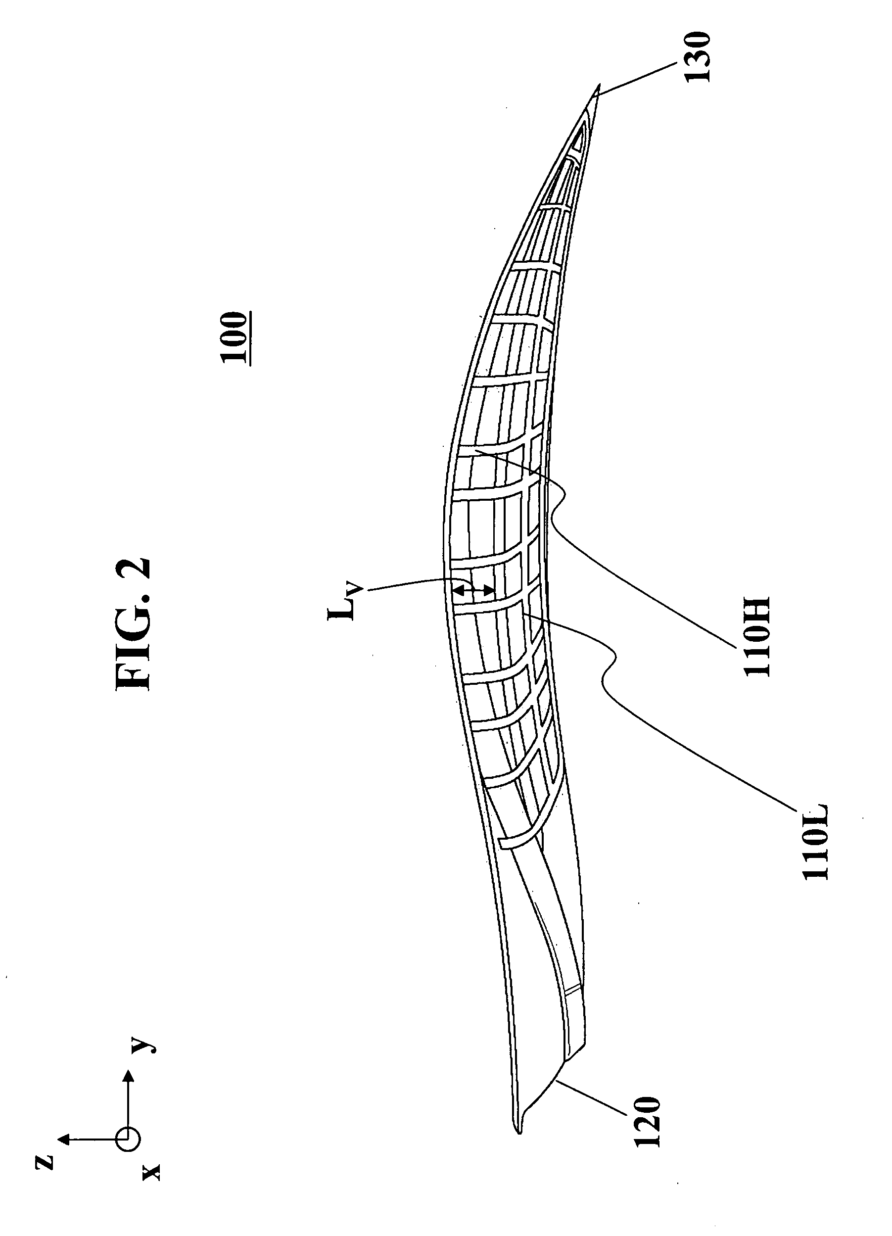
[0051]FIGS. 6 and 7 are front and side views, respectively, of the arch support orthotic device including the plurality of honeycomb support structures according to the present invention. In this exemplary embodiment, the arch support orthotic device 200 can be constructed of polypropylene, or other relatively hard or rigid plastic material. As shown in FIGS. 6 and 7, the arch support orthotic device 200 tapers in thickness along its length and width of the arch support orthotic device 200 to accommodate the wearer's comfort. The honeycomb arch support structures 210 will prevent collapsing of the arch support region 260 directly against the shoe inner sole surface (not shown) and thus maintain the desired supporting function. In this exemplary embodiment, the length (in the vertical direction) of the supporting structures LV increases gradually from the distal end 230 to the proximal end 220. The size (width of the inner portion) of each honeycomb is typically 0.5 to 0.75 inches. T...

fourth embodiment

[0053]FIGS. 8A and 8B are bottom views of arch support orthotic devices including the plurality of honeycomb support structures according to third and fourth embodiment of the present invention. As shown in FIGS. 8A and 8B, the arch support orthotic device 300 or 400 can include a non-slip pad 370 and 470 that can prevent slipping of the arch support orthotic device 300 or 400 against an inner sole surface of a footwear. Accordingly, even when the size the arch support orthotic device 300 or 400 is less than 100% of the shoes, the arch support orthotic device 300 or 400 would not slip within the shoes.

[0054]In general, the closer together the support structures, the more supportive the device and the more rigid the arch support region 360 and 460. In addition, the greater the width of the arch support structures, the more supportive the device and the more rigid the arch support region 360 and 460. Therefore, based on particular preferences of the manufacturer and on the market dema...


PUM


Abstract

An arch support orthotic device comprises an upper surface facing a wearer's foot, and a lower surface facing a footwear, wherein the upper surface is formed of a deformable semi-rigid material responding flexibly to a weight of the wearer, and wherein the lower surface comprises an arch support section facing an inner sole surface of the footwear including a plurality of support structures that performs an arch supporting function, controls a deformability of the orthotic device so as to reduce loss of the arch supporting function when worn by the wearer, and prevents substantial deformation against the inner sole surface of the footwear.

Description

[0001]This application is a Continuation in Part and claims the benefit of U.S. patent application Ser. No. 11 / 544,411, filed on Oct. 4, 2006, which claims the benefit of U.S. Provisional Patent Application No. 60 / 839,775, filed on Aug. 24, 2006, which are hereby incorporated by reference.BACKGROUND OF THE INVENTION[0002]1. Field of the Invention[0003]The present invention relates to the field of arch support orthotics for feet, and more particularly to arch support orthotics having a patterned surface on the underside of the arch curve.[0004]2. Discussion of the Related Art[0005]Typical prior art arch support orthotics are available in a variety of materials such as cushioning materials, leather, resilient plastic, rubber, foam, or metal that are designed to fit into the footwear of a patient. They typically are shaped in the form of the human foot arch with proximal ends (heel region) and distal ends (toe region) sloped down laterally from the arch support region. The shape of the...

Claims


Application Information

Patent Timeline
IPC IPC(8): A43B7/22A43B13/38A43B7/14A43B7/16
CPCA43B1/0009A43B7/141A43B7/142A43B17/18
Inventor CONFORTI, JEFFREYGUADARA, JOHNKIM, MINGOO
Owner BODY TECH LAB
Why Eureka
Try Eureka