Embroidery frame support device

a support device and embroidery frame technology, applied in the direction of embroidering machines, automatic machines, textiles and paper, etc., can solve the problems of affecting the operation efficiency of the embroidery frame, the front end portion of the embroidery frame bending, and the harmful influence of the sewing operation, etc., to achieve the effect of easily changing the embroidery frame of a different typ

Inactive Publication Date: 2009-03-19
TOKAI IND SEWING MACH CO LTD
View PDF6 Cites 2 Cited by
  • Summary
  • Abstract
  • Description
  • Claims
  • Application Information

AI Technical Summary

Benefits of technology

[0012]According to the present invention, the embroidery frame support device is constructed so that the base member is fixedly attached to the predetermined portion of the embroidery sewing machine, the support member is supported on the base member so as to be capable of moving relatively with the base member, and the free end of the embroidery frame is movably supported to the support member. Thus, it is possible to attach the embroidery frame support device to the embroidery sewing machine while the support member and the base member are integrated. In addition, it is possible to release the embroidery frame support device from the embroidery sewing machine. Since the support member and the base member are integrated, the present invention achieves a brilliant effect that it is possible to omit work of alignment when the embroidery frame support device is attached, and the attaching and releasing operation of the embroidery frame support device itself can be carried out easily. Further, in the case where the embroid

Problems solved by technology

This causes the front end portion of the embroidery frame to bend, and defect that a harmful influence is exerted on a sewing operation has occurred.
A removing operation of the embroidery frame support device is a complicated operation in which the support arm of the embroidery frame support device is released from the Y direction drive element and the linear guide of the support arm is released from the cylinder bed.
Further, in an attaching operation of the embroidery frame support device, it requires t

Method used


Image

  • Embroidery frame support device
  • Embroidery frame support device
  • Embroidery frame support device

Examples


Embodiment Construction

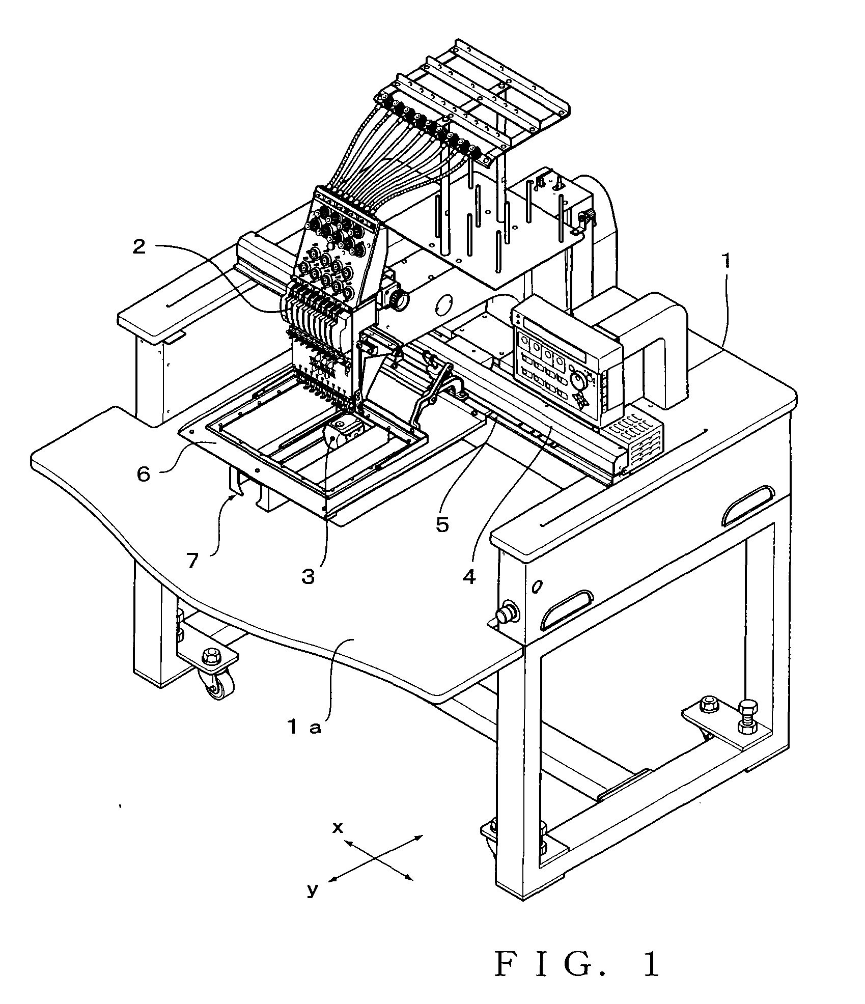
[0024]One embodiment of the present invention will hereinafter be described with reference to the accompanying drawings.

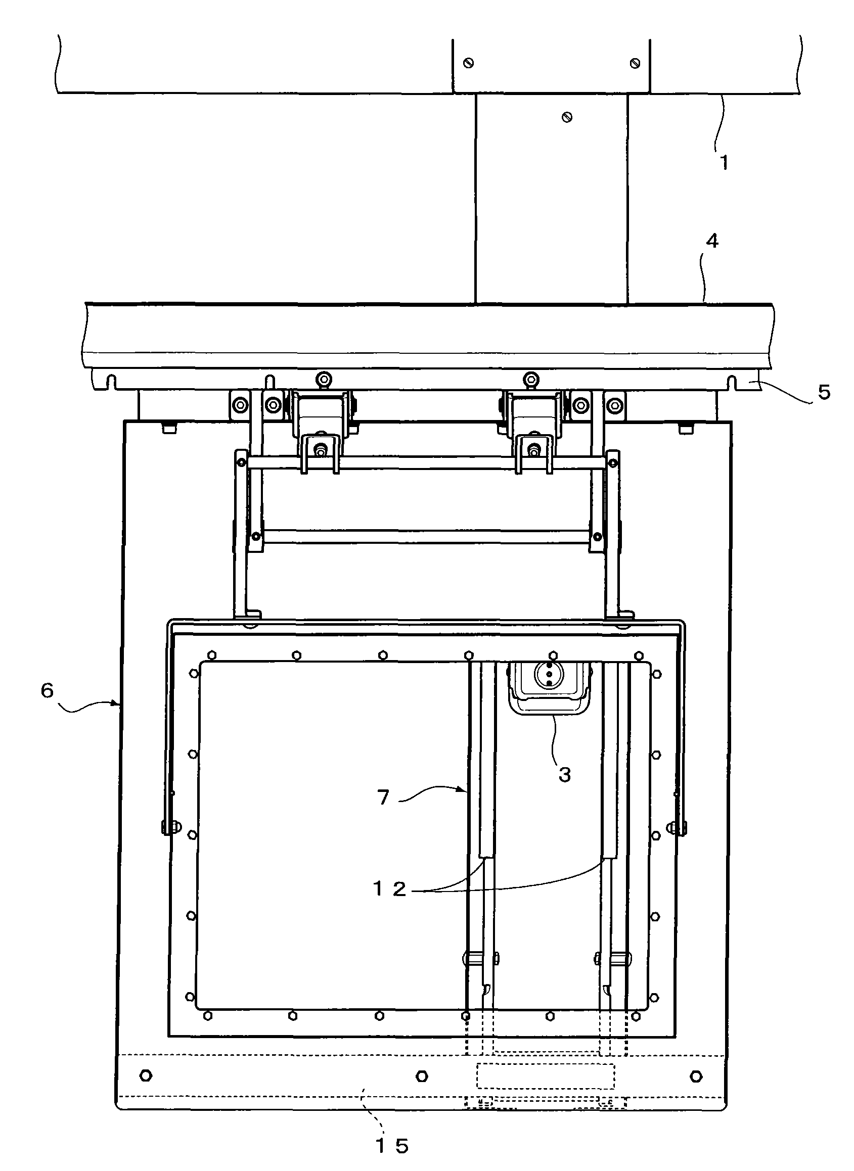
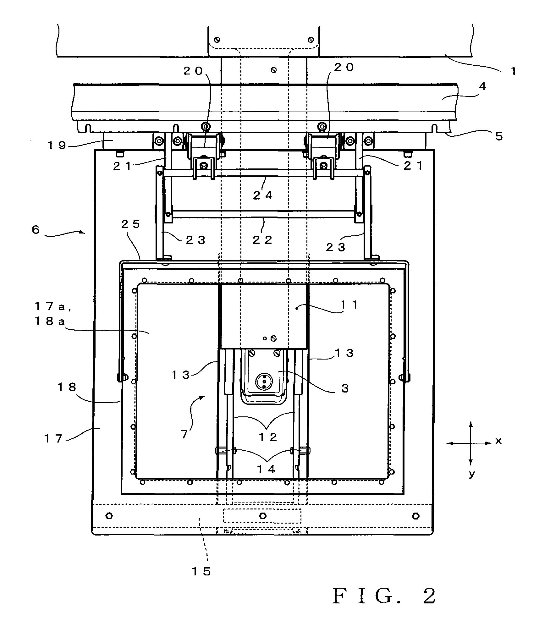
[0025]FIG. 1 is an overall perspective view showing a single-head embroidery sewing machine according to the present embodiment when viewed from a forward oblique upper side thereof. In the present embodiment, when the sewing machine is viewed from the front surface thereof, a right-and-left (horizontal) direction thereof is referred to as an “X direction”, while a front-and-behind direction thereof is referred to as a “Y direction”. In FIG. 1, a reference numeral 1 denotes a sewing machine table, a reference numeral 2 denotes a sewing machine head, and a reference numeral 3 denotes a cylinder bed. A front portion (front table) la of the sewing machine table 1 is configured to be capable of displacing upward and downward in a similar manner to this type of sewing machine known in the prior art. By displacing the front table la toward a lower position, it is possibl...


PUM


Abstract

In an embroidery sewing machine, an embroidery frame support device for supporting a front end portion of an embroidery frame installed in a cantilevered manner includes: a base member that is a base for attaching the embroidery frame support device to the embroidery sewing machine, and a Y slide rail (support member) having a movable end that can move relatively with the base member. The embroidery frame support device supports a front end portion of the embroidery frame from a lower surface thereof through an X slide rail attached to a tip portion of the Y slide rail. The embroidery frame support device can be attached to the embroidery sewing machine by screwing a base member to a cylinder bed. The screwing of the base member to the cylinder bed can be carried out from the upper side of a sewing machine table.

Description

[0001]This application is a U.S. National Phase Application of PCT International Application PCT / JP2006 / 310052 filed on May 19, 2006.TECHNICAL FIELD [0002]The present invention relates to an embroidery frame support device for supporting attachment of an embroidery frame that holds an embroidered object in an embroidery sewing machine, by which an embroidery operation can be carried out against a tubular embroidered object such as a T-shirt and a cap.BACKGROUND ART [0003]Heretofore, in an embroidery sewing machine, when an embroidery operation is carried out against a tubular embroidered object such as a T-shirt and a cap, the embroidery sewing machine is constructed so that an embroidery frame for supporting the embroidered object is supported in a cantilevered manner. For example, when the embroidery operation is carried out against a T-shirt, a sweat shirt or the like, the embroidery frame is supported by a holding arm that protrudes in a cantilevered manner from a frame drive el...

Claims


Application Information

Patent Timeline
IPC IPC(8): D05C9/04
CPCD05C9/06D05C9/04
Inventor TAJIMA, IKUOYOSHIMURA, TOMOAKIFUJIMORI, TAKEO
Owner TOKAI IND SEWING MACH CO LTD
Why Eureka
Try Eureka