Ventilation Member and Ventilation Structure

a technology of ventilation member and ventilation structure, which is applied in ventilation systems, electrical apparatus casings/cabinets/drawers, separation processes, etc., can solve the problems of relatively difficult for foreign matter to remain on the cylindrical side wall portion of the cover part, and undesirably increase the overall size of the ventilation member, so as to reduce the possibility of foreign matter adhesion, increase the dimension of the support body, and high permeability

Inactive Publication Date: 2009-04-30
NITTO DENKO CORP
View PDF7 Cites 12 Cited by
  • Summary
  • Abstract
  • Description
  • Claims
  • Application Information

AI Technical Summary

Benefits of technology

[0007]The ventilation member of the invention as described above is configured in such a manner that the ventilation membrane is disposed to the side surface portion of the support body in a positional relationship in which the ventilation membrane faces the cylindrical side wall portion of the cover part. When configured in this manner, it is possible to increase the opening area of the second opening to be covered with the ventilation membrane, that is, the ventilation area, without having to increase the dimension of the support body significantly. Also, even in a case where foreign matter, such as water droplets, enters into the cover part, it is relatively difficult for the foreign matter to remain on the cylindrical side wall portion of the cover part. Accordingly, by adopting an arrangement that allows the cylindrical side wall portion of the cover part and the ventilation membrane to face each other, it is possible to reduce the possibility of adhesion of foreign matter onto the ventilation membrane. As has been described, the ventilation member of the invention is compact yet achieves high permeability and excels in against exposure to foreign matter, such as water droplets and dust.

Problems solved by technology

However, as can be readily understood from FIG. 12A and FIG. 12B, enlarging the opening area in the cylindrical body can undesirably increase the overall size of the ventilation member.
Also, even in a case where foreign matter, such as water droplets, enters into the cover part, it is relatively difficult for the foreign matter to remain on the cylindrical side wall portion of the cover part.

Method used


Image

  • Ventilation Member and Ventilation Structure
  • Ventilation Member and Ventilation Structure
  • Ventilation Member and Ventilation Structure

Examples


first embodiment

[0021]Hereinafter, embodiments of the invention will be described with reference to the accompanying drawings.

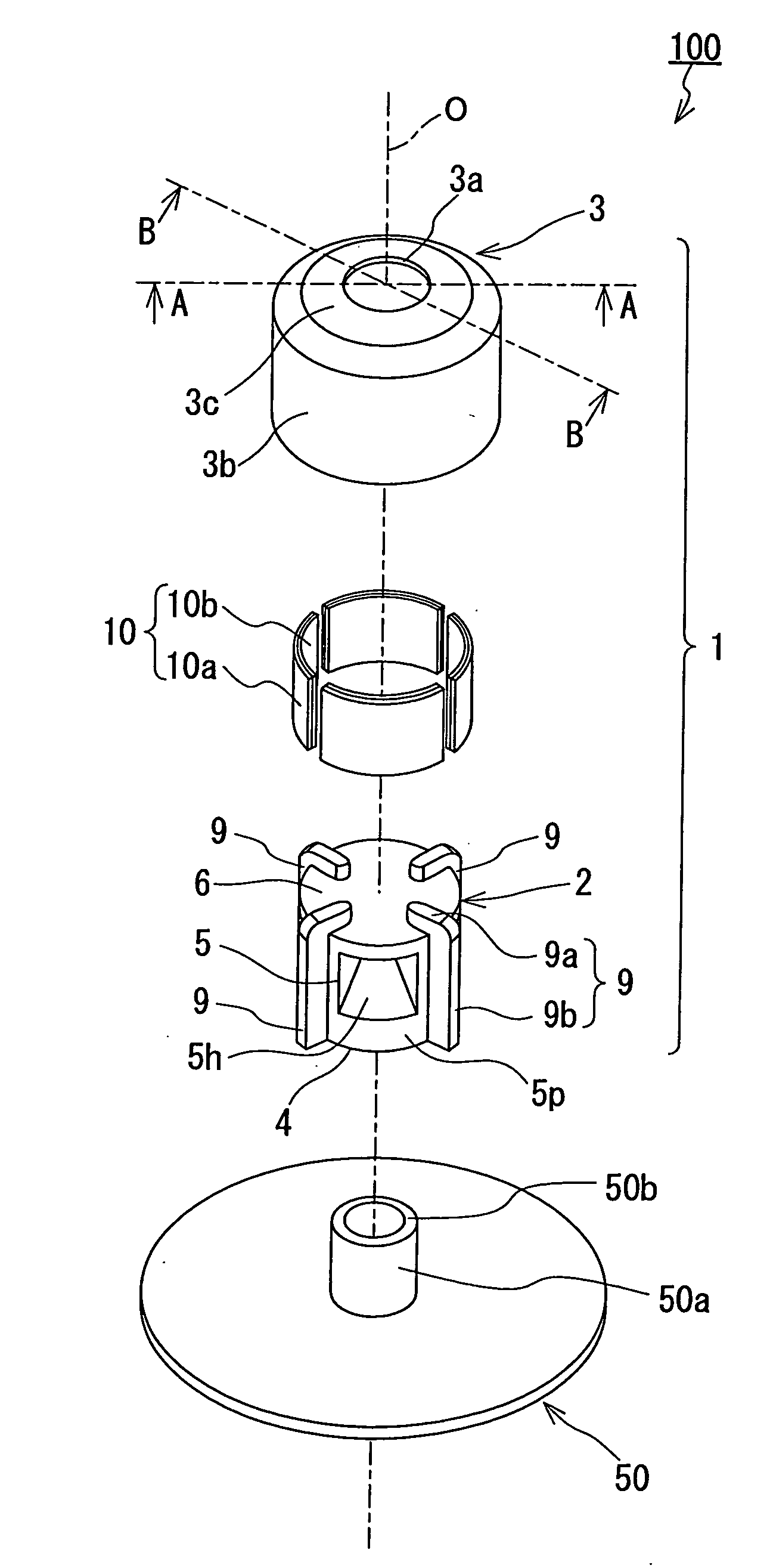
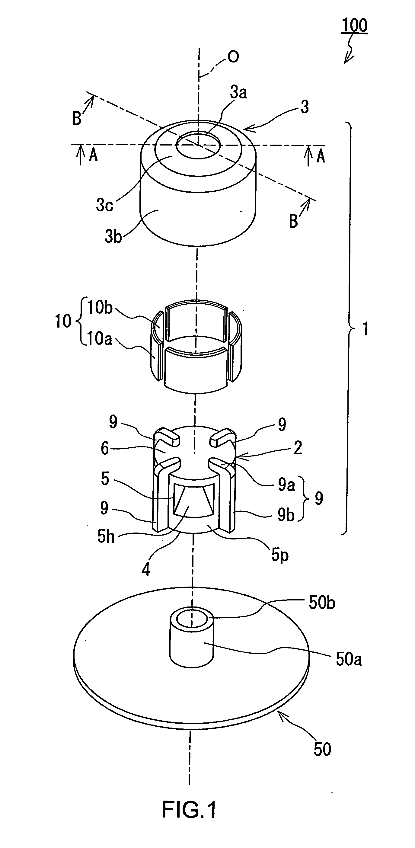
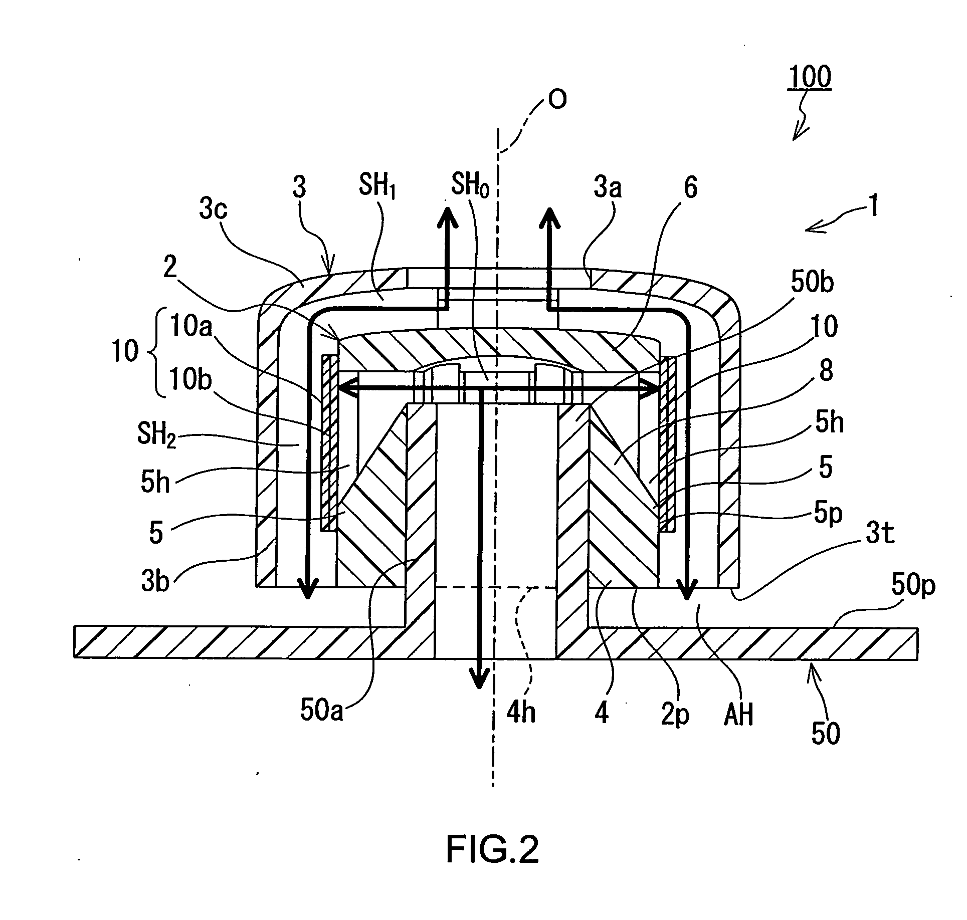
[0022]FIG. 1 is an exploded perspective view of a ventilation member and a ventilation structure of the invention. FIG. 2 is a view showing a state where the ventilation member is installed on a casing, that is, a cross section of the ventilation structure taken on line A-A. FIG. 3 is another cross section taken on line B-B. In FIG. 2, an air circulation channel is indicated by thick arrows (the same applies to FIG. 6 and FIG. 10).

[0023]The ventilation member 1 is installed on an opening part 50a of a casing 50, for example, of an electrical component for automobile, and thereby forms a ventilation structure 100 to enable ventilation between the interior and the exterior of the casing 50. The opening part 50a of the casing 50 is of a configuration in the shape of a nozzle that is convex toward the exterior of the casing 50. The ventilation member 1 is fixed to the casing 50 ...

second embodiment

[0051]FIG. 5 is an exploded perspective view of a ventilation member of a second embodiment. FIG. 6 is a cross section taken on line A-A of FIG. 5 and FIG. 7 is a cross section taken on line B-B of FIG. 5. As is shown in FIG. 5, a ventilation member 21 includes a support body 22, ventilation membranes 10, and a cover part 3, and forms a ventilation structure 102 when installed on the opening part 50a of the casing 50 to enable ventilation between the interior and the exterior of the casing 50. The ventilation membranes 10 and the cover part 3 are common with those in the first embodiment above. A major difference is the structure of the support body 22.

[0052]As are shown in FIG. 5 through FIG. 7, the support body 22 of the ventilation member 21 is of a configuration in the shape of a column, and includes a bottom surface portion 24 to be connected to the casing 50, a side surface portion 25 on which the ventilation membranes 10 are installed, a top portion 26 positioned on the side ...


PUM

PropertyMeasurementUnit
pore diameteraaaaaaaaaa
thicknessaaaaaaaaaa
lengthaaaaaaaaaa

Abstract

A ventilation member (1) comprises a support body (2), a ventilation membrane (10), and a cover part (3). The support body (2) includes a bottom surface portion (4) connected to the casing (50) and a side surface portion (5) on which the ventilation membrane (10) is installed. A first opening (4h) is formed in the bottom surface portion (4), and a second opening (5h) is formed in the side surface portion (5). The ventilation membrane (10) is installed on the side surface portion (5) so as to close the second opening (5h). The cover part (3) has a cylindrical side wall part (3b) that circumferentially surrounds the support body (2) in such a state that the support body (2) is assembled therein. The position of the second opening (5h) to be formed in the side surface portion (5) of the support body (2) is adjusted so that the ventilation membrane (10) is protected when the membrane faces the cylindrical side wall part (3b).

Description

TECHNICAL FIELD[0001]The present invention relates to a ventilation member to be attached to a casing. The invention also relates to a ventilation structure using the ventilation member.BACKGROUND ART[0002]A ventilation member is installed on a casing that accommodates electric components for an automobile, such as lamps, motors, sensors, and an ECU. Such a ventilation member has the function of ensuring ventilation between the interior and the exterior of the casing, the function of easing a change in pressure inside the casing caused by a temperature change, and the function of inhibiting the entrance of foreign matter into the casing. Examples of such a ventilation member are disclosed in JP-A-2001-143524 and JP-A-10-85536.[0003]For example, a ventilation member 60 disclosed in JP-A-2001-143524 is formed of a cover part 61 in the shape of a bottomed cylinder, a cylindrical body 62 made of rubber, and a ventilation membrane 63 as are shown in FIG. 12A and FIG. 12B. The cylindrical...

Claims


Application Information

Patent Timeline
Patent Type & Authority Applications(United States)
IPC IPC(8): H05K7/20
CPCF21S48/335H05K5/0213F21V31/03H05K5/068F21S45/30H05K5/0216B60R16/0239H02K5/10H02K2205/09B60Y2410/10
Inventor YANO, YOUZOU
Owner NITTO DENKO CORP
Why Eureka
Try Eureka