Work Clamp and Wire Bonding Apparatus

a technology of wire bonding apparatus and clamp, which is applied in the direction of soldering apparatus, manufacturing tools,auxillary welding devices, etc., can solve the problems of insufficient restraint of oxidation of bonding area, so as to reduce the amount of antioxidant gas used, the effect of restrainting oxidation of the bonding area

Active Publication Date: 2009-05-28
KAIJOO KK
View PDF20 Cites 6 Cited by
  • Summary
  • Abstract
  • Description
  • Claims
  • Application Information

AI Technical Summary

Benefits of technology

[0033]As mentioned above, according to the present invention, a work clamp and a wire bonding apparatus that can suf

Problems solved by technology

As a result, the oxidation of the bonding area can not be sufficiently restrained.
Further, with the conventional work clamp,

Method used


Image

  • Work Clamp and Wire Bonding Apparatus
  • Work Clamp and Wire Bonding Apparatus
  • Work Clamp and Wire Bonding Apparatus

Examples


Embodiment Construction

[0068]An embodiment of the present invention will be described below referring to the attached drawings.

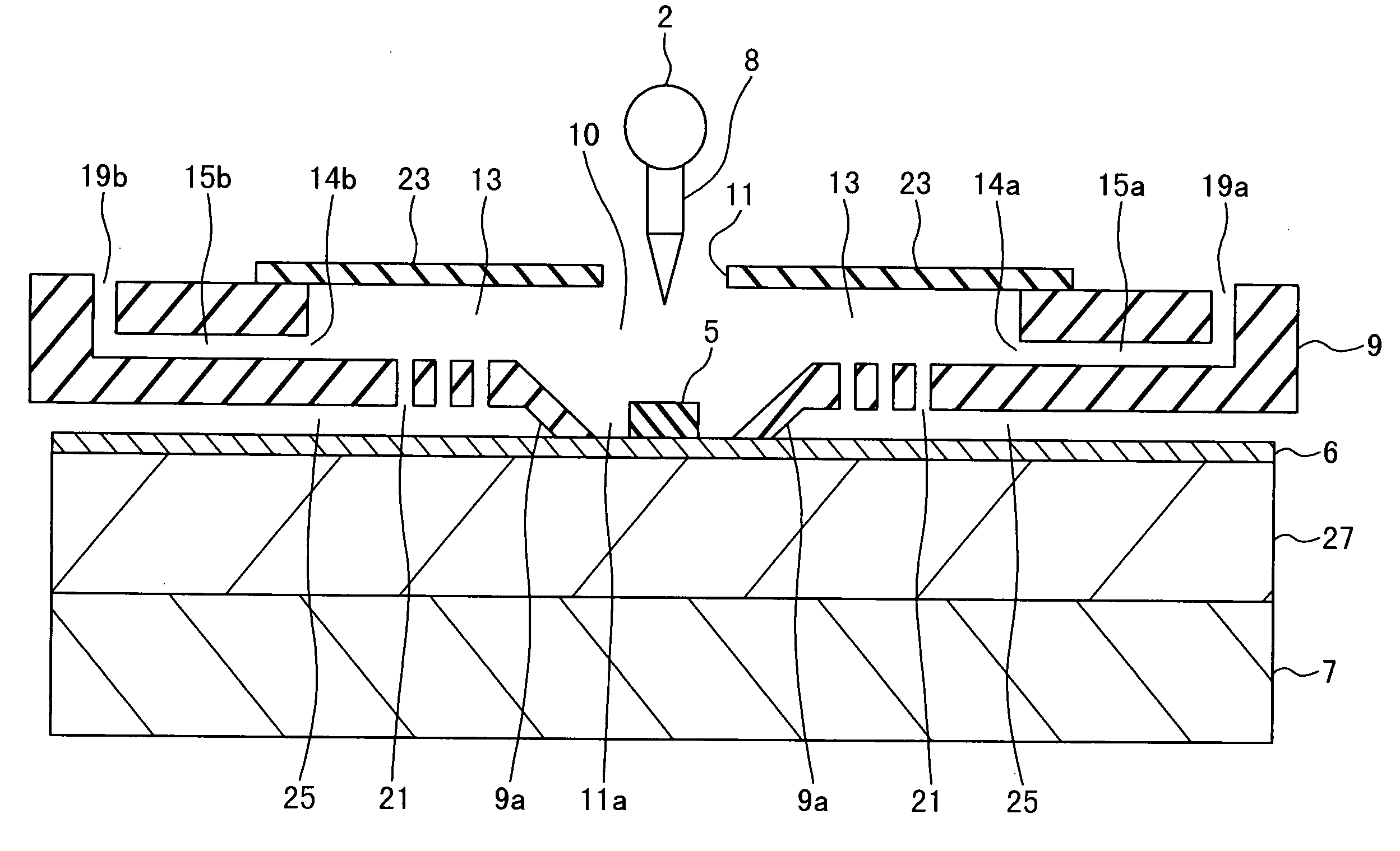
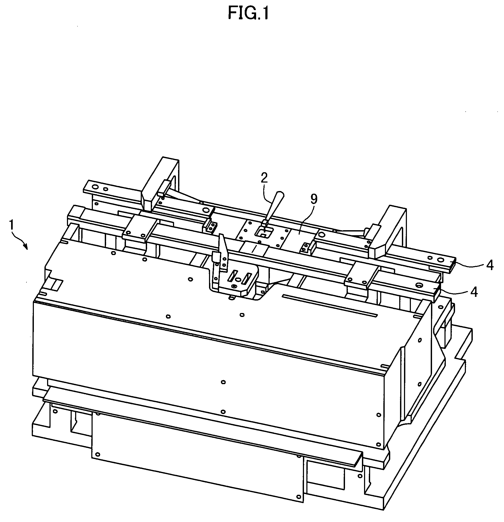
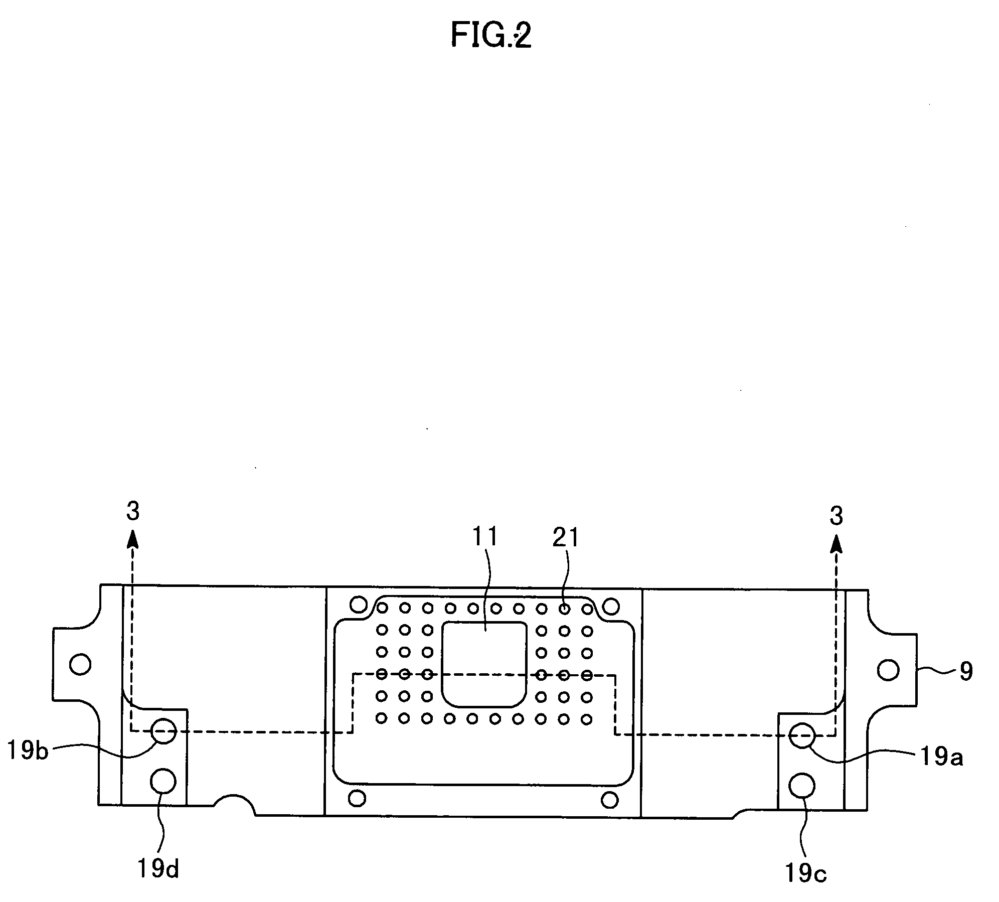
[0069]FIG. 1 is a perspective view illustrating a wire bonding apparatus according to the embodiment of the present invention. FIG. 2 is a top view of a work clamp shown in FIG. 1. FIG. 3 is a sectional view illustrating a state where a work is held on a stage by the work clamp shown in FIG. 2 for carrying out bonding and shows a portion corresponding to a section of the work clamp along an arrow 3-3 in FIG. 2. FIG. 4A is a sectional view obtained by cutting the work clamp shown in FIG. 2 on a face along a gas path.

[0070]As shown in FIG. 1, a wire bonding apparatus 1 has a bonding head 2, a work clamp 9, and a rail 4. Below the work clamp 9, a bonding stage is arranged. A lead frame 6 shown in FIG. 3 on which a bonding chip 5 is mounted is a work to be bonded. Such works continued in plural are moved on the rail 4, a bonding area of the work (that is, a lead portion at the bonding...


PUM

PropertyMeasurementUnit
Areaaaaaaaaaaa

Abstract

A work clamp and a wire bonding apparatus that can sufficiently restrain oxidation of a bonding area even while reducing a use amount of antioxidant gas are provided. The work clamp according to the present invention includes an interior hollow portion 10 providing an atmosphere of the antioxidant gas, a lower opening portion 11a provided below the interior hollow portion, for containing the bonding area in the interior hollow portion, an upper opening portion 11 provided above the interior hollow portion, for exposing the bonding area, a cavity 13 covering the interior hollow portion and having an area larger than an opening area of the upper opening portion, gas introduction ports 14a, 14b provided at the cavity, for introducing the antioxidant gas into the cavity, and holes 21 connected to below the cavity, for blowing the antioxidant gas introduced from the gas introduction port to a portion other than the bonding area of the work.

Description

TECHNICAL FIELD[0001]The present invention relates to a work clamp and a wire bonding apparatus using the same and particularly to a work clamp and a wire bonding apparatus that can sufficiently restrain oxidation of a bonding area even while reducing a use amount of antioxidant gas.BACKGROUND ART[0002]FIG. 5 is a sectional view illustrating a work clamp of a conventional wire bonding apparatus. This work clamp has a mechanism of preventing oxidation of copper if an object of bonding is a bare copper lead frame or if a bonding wire is copper. This mechanism introduces an inert gas such as nitrogen gas into an opening 17 leading to a bonding area.[0003]A semiconductor device in a form of a lead frame 12 holding a die 18 is arranged on a platform or an upper plate 29 of a wire bonding apparatus. The upper plate 29 has a heating mechanism for raising a temperature of the lead frame 12. A wind clamp 16 fixes the lead frame 12 onto the upper plate 29. The opening 17 of the wind clamp 16 ...

Claims


Application Information

Patent Timeline
IPC IPC(8): B23K31/02
CPCB23K20/004B23K37/0435Y10S228/904H01L2924/15747H01L2924/01006H01L2924/01005H01L2924/01082H01L2924/01078H01L2924/01033B23K2201/40H01L24/45H01L24/78H01L24/85H01L2224/45147H01L2224/48247H01L2224/78301H01L2224/78703H01L2224/78801H01L2224/85065H01L2224/85075H01L2924/01004H01L2924/01007H01L2924/01015H01L2924/01018H01L2924/01029H01L2924/00H01L2924/00011B23K2101/40H01L24/48H01L2224/781H01L2924/00014H01L2924/00012
Inventor JINDO, RIKIYOSHINO, HIDEKIKUSHIMA, MAMI
Owner KAIJOO KK
Why Eureka
Try Eureka