Personal air conditioning apparatus

a technology of air conditioning apparatus and air conditioner, which is applied in the direction of lighting and heating apparatus, ventilation systems, heating types, etc., can solve the problems of reducing the thermal efficiency of many prior art devices, ice or a replacement container of freezable liquid, and not being readily available to recharge the device. , to achieve the effect of improving cooling performance, economic construction and effective and efficient operation

Inactive Publication Date: 2009-06-04
C ENTERPRISE HK
View PDF8 Cites 13 Cited by
  • Summary
  • Abstract
  • Description
  • Claims
  • Application Information

AI Technical Summary

Benefits of technology

[0019]This invention provides a device for personal cooling which is effective and efficient in operational use, and which by accumulating cooled air which is lost in typical prior art designs, provides for improved cooling performance. The device may be economically constructed and has an overall simple design which minimizes manufacturing costs.

Problems solved by technology

The thermal efficiency of many of these prior art devices is reduced by features which allow air cooled by contact with the cold surface to be lost to the user, for instance after placement of the cooling element and before the fan is operated.
These devices use axial fans and typically have no structure to retain this cool air from the cooling element, and so allow this cooled air to escape.
A further drawback of these personal cooling devices is that ice, or a replacement container of freezable liquid, may not be readily available to recharge the device.

Method used


Image

  • Personal air conditioning apparatus
  • Personal air conditioning apparatus
  • Personal air conditioning apparatus

Examples


Embodiment Construction

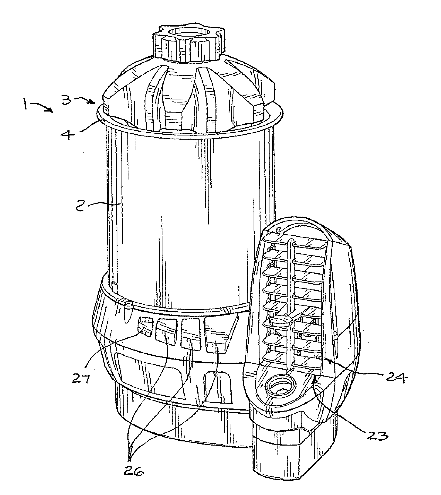
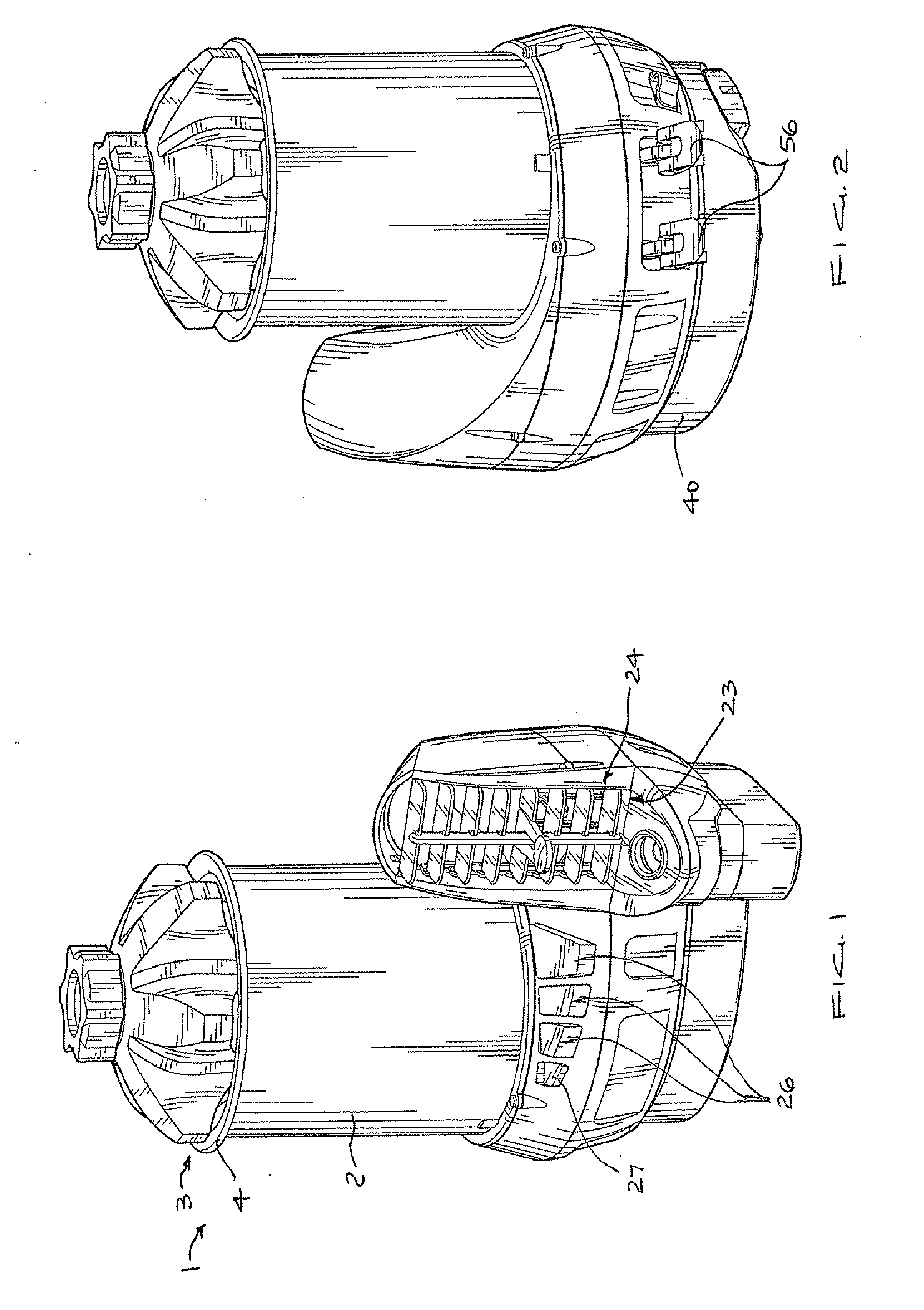
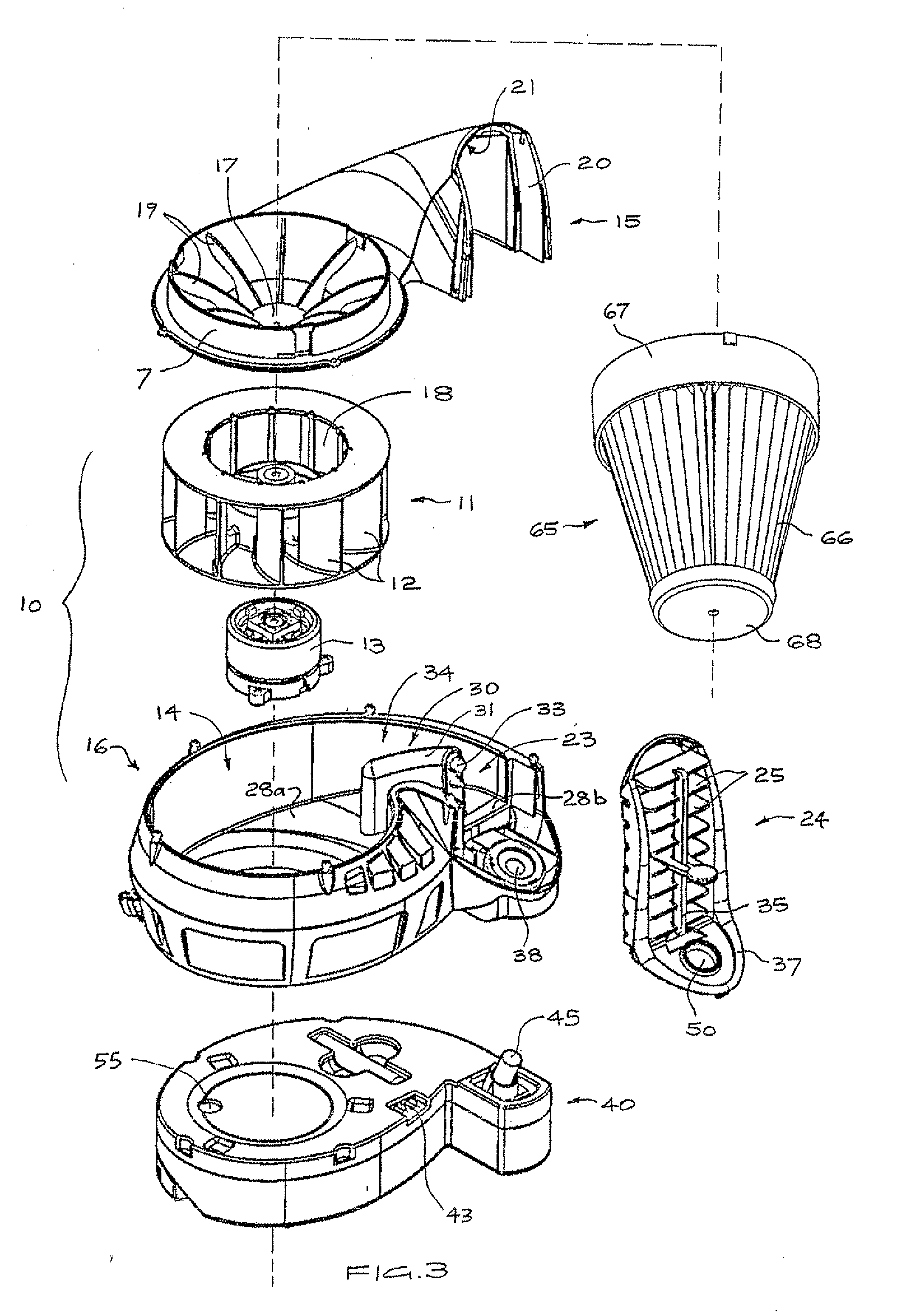
[0028]Referring to the drawings, a cordless personal cooling apparatus 1 includes a tubular container 2 with an open top end 3 and an outwardly tapered lip 4. The container 2 has a central axis 5 and an open bottom end 6 axially opposing the top end 3. The bottom end 6 is removably received in an annular flange 7 formed on the upper, outer end of a scroll casing 10. Axially elongated ribs 8 project inwardly from the walls of the container 2 and are angularly spaced apart. The ribs 8 serve to define air flow channels and to centrally locate a coolant member having cylindrical walls, and which may take the form of a chilled and sealed beverage can 9a (shown in section in FIG. 4) or a vessel 9b (shown protruding from the container 2 in FIG. 1) holding a liquid with a low freezing temperature, such as a water and glycol mix. The vessel 9b includes circumferentially spaced protrusions 46 which are supported upon the rim of the container 2 and define recesses 47 therebetween. The containe...


PUM


Abstract

A personal air conditioning apparatus includes a centrifugal fan received within a scroll casing. A container mounted to the inlet of the scroll housing is provided for receiving and holding a coolant member. The scroll casing is supported upon a base enclosing two liquid reservoirs and a battery compartment. A liquid atomizing device fed from one of the reservoirs dispenses liquid droplets into air flow from a discharge passage. A channel extends between the container and the other of the reservoirs for draining away condensation formed on the coolant member. The scroll casing defines the discharge passage, which has a cross-sectional area that increases toward an outlet at an end of the scroll casing. Axially opposing faces of the discharge passage are divergent, and the cross section of the discharge passage adjacent the outlet has a shape elongated substantially in the axial direction. The inner end of the container lies above the scroll casing and a surface bounding the lower side of the discharge passage is inclined upwardly from the inlet toward the outlet. The coolant member may be a chilled beverage can and, when the fan is not operating, cooled air drops into the fan where it is retained.

Description

TECHNICAL FIELD[0001]The present invention relates to air conditioning apparatus, and more particularly concerns methods and apparatus for generating, purifying, cooling or heating and directing a flow of air for the comfort of the user.BACKGROUND OF THE INVENTION[0002]In hot climates and during summer in more temperate climates, personal cooling is a concern for many people undertaking activities where they are exposed to high ambient temperatures. For personal cooling applications one class of prior art devices incorporate a fan that blows air either through ice supported so as to be air-permeable, or through channels in a plastic container of a type for holding a freezable liquid. The thermal efficiency of many of these prior art devices is reduced by features which allow air cooled by contact with the cold surface to be lost to the user, for instance after placement of the cooling element and before the fan is operated. These devices use axial fans and typically have no structur...

Claims


Application Information

Patent Timeline
Patent Type & Authority Applications(United States)
IPC IPC(8): F24F13/08F24F13/00F24F1/0059
CPCF24F5/0035Y02B30/545F24F2221/38F24F2001/0088F24F1/0007Y02B30/54F24F1/0059
Inventor TAM, CHEUK HUNGELSWORTHY, CHRISTOPHER THOMAS
Owner C ENTERPRISE HK
Why Eureka
Try Eureka