Culinary chipping, slicing and dicing tool

Active Publication Date: 2019-08-22
MAXPAT TRADING & MARKETING FAR EAST LTD
View PDF0 Cites 3 Cited by
  • Summary
  • Abstract
  • Description
  • Claims
  • Application Information

AI Technical Summary

Benefits of technology

[0025]This invention provides a device which is effective and efficient in operational use, and which can be readil

Problems solved by technology

Although the above culinary tool is generally suitable for dicing and slicing, it has a number of drawbacks.
Further, the tool itself is quite complicated, with the second pusher and associated guides and return springs not only adding to manufacturing cost but also making cleaning and reassembly time consumin

Method used


Image

  • Culinary chipping, slicing and dicing tool
  • Culinary chipping, slicing and dicing tool
  • Culinary chipping, slicing and dicing tool

Examples


Example

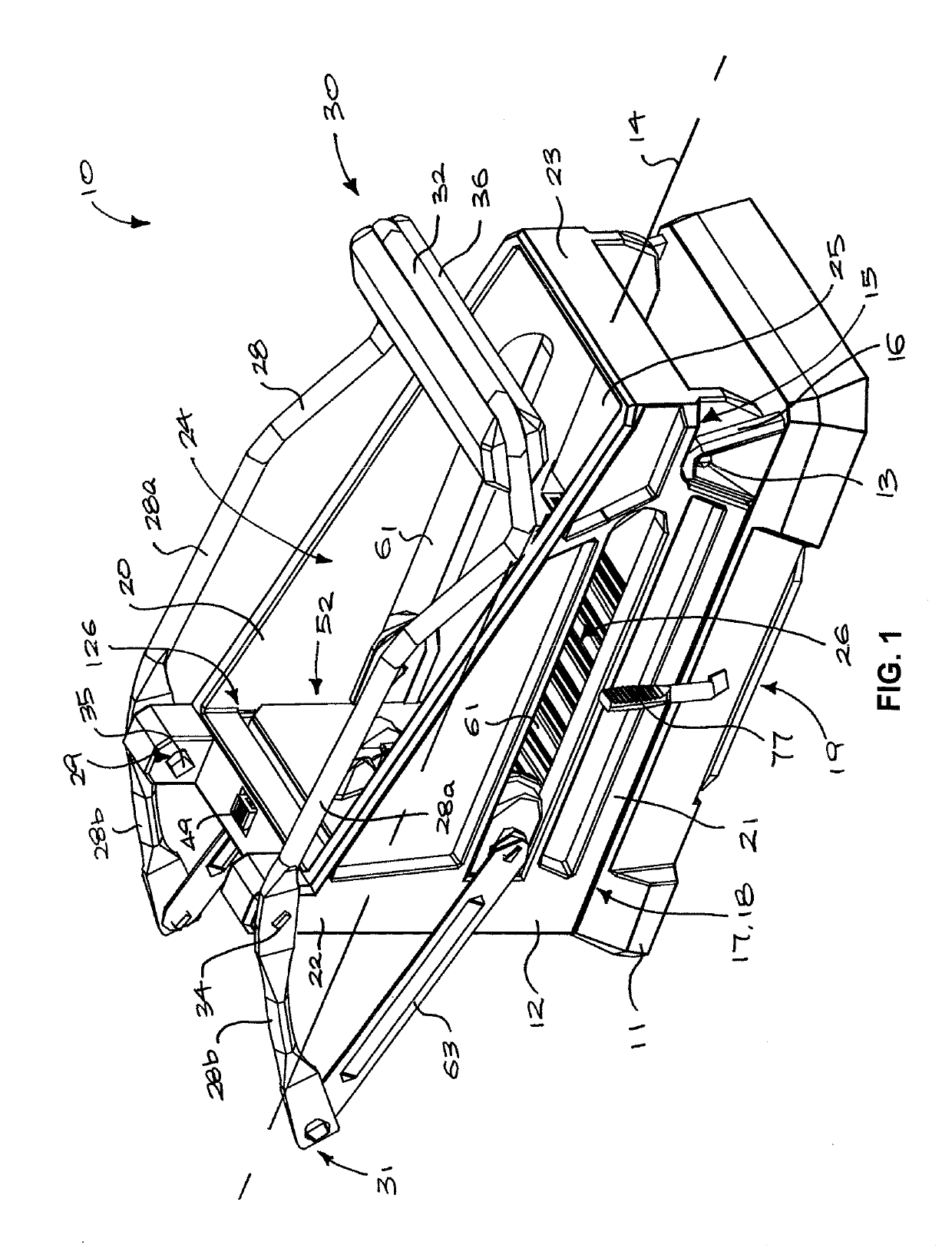
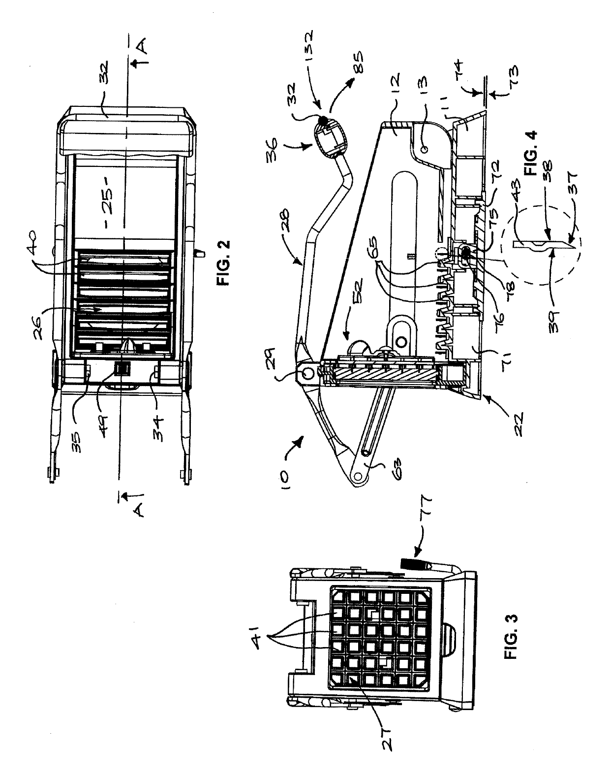
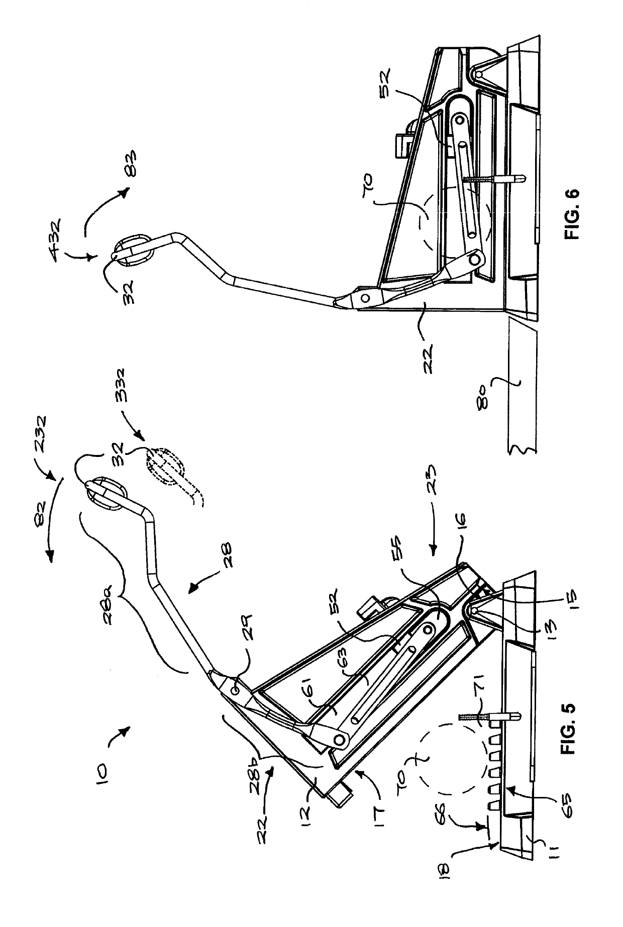
[0035]Referring to FIGS. 1 and 5, a culinary tool 10 generally comprises a base 11 connected to a frame 12 by a hinge 13 to turn between an open position (FIG. 5) in which the frame 12 and base 11 are spaced apart, and a closed position (FIG. 1) in which the frame 12 rests on the base 11.

[0036]The frame 12 may have a generally rectangular prismatic form, with a long axis 14 orthogonal to the transverse axis of the hinge 13, the hinge 13 being disposed near one longitudinal end of the frame 12 and base 11. Stop surfaces 15, 16 on the frame and base, respectively, may abut to limit the relative angle of rotation about the hinge 13 in the direction of opening and provide a stable inclined position for the frame 12. Complementary surfaces 17, 18 on the frame and base, respectively, may abut in the closed position, whereby the frame 12 is supported on the base 11 with the axis 14 horizontal. A suction cup assembly 19 may be mounted in a centrally located recess in the base 11 for securin...


PUM


Abstract

A culinary tool for slicing and dicing, includes a base connected by a hinge to a frame that carries two cutting grids. A drive mechanism connects a pivoting handle to a pusher such that pivoting of the handle relative to the frame drives displacement of the pusher and the turning of the frame between the open and closed positions, and a forward stroke turns the frame about the hinge toward the base, pressing the item through the first cutting grid, and a reverse stroke moves the pusher to the one of the ends of the cavity, pressing the item through the second cutting grid.

Description

TECHNICAL FIELD[0001]The present invention relates to a culinary tool that both slices and dices food, such as vegetables, fruit, and cheese.BACKGROUND OF THE INVENTION[0002]Dicing manually involves making parallel cuts in three sets, the cutting directions of each set being orthogonal. To produce cubes, the spacing of cuts must be even and, if using a knife, the item to be cut must be turned at least once, so culinary hand tools continue to maintain a place in many kitchens, despite the proliferation of electrically powered food processors, because of their capacity to perform tasks such as dicing.[0003]U.S. Pat. No. 7,587,968 describes a culinary hand tool including two orthogonal cutting grids through which an item is pressed sequentially to dice it into cubes: a first cutting grid that is upright and has square openings and a second that is horizontal with rectangular openings. A pivoting handle drives a horizontal pusher to press the item through the first grid and, with contin...

Claims


Application Information

Patent Timeline
IPC IPC(8): B26D3/18A47J43/25B26D7/06B26D3/26B26D7/01
CPCB26D3/185A47J43/25B26D7/065B26D3/26B26D7/0608B26D7/01B26D2210/02B26D3/18
Inventor CHAN, SHU TONG
Owner MAXPAT TRADING & MARKETING FAR EAST LTD
Why Eureka
Try Eureka