Arc-cutting guide for a portable powered hand tool

a portable, hand tool technology, applied in the direction of manufacturing tools, metal-working machine components, metal working apparatuses, etc., can solve the problems of increasing the cost of clamping, obstructing the path traced by the user's hand and lower arm, and the knob adjacent to the handle is difficult to use, so as to achieve convenient and accurate measurement. , the effect of effective and efficient operation

Inactive Publication Date: 2009-02-12
CHOON NANG ELECTRICAL APPLIANC
View PDF7 Cites 5 Cited by
  • Summary
  • Abstract
  • Description
  • Claims
  • Application Information

AI Technical Summary

Benefits of technology

[0022]Preferably the slider member includes a longitudinally-extending rib received in the channel with a longitudinally-extending flange on either transverse side of the rib, each flange being provided with respective measuring indicia to be read against a measuring mark on one transverse side of the swing arm. The swing arm and rib thus provide a physical and visual separation between the scales, allowing ready accurate measurements to be made with the slider in either orientation.
[0023]This invention thus provides an arc-cutting guide which is effective and efficient in operational use. By making both the knob and handle captively retained they cannot ordinarily become separated from the guide. Mounting both knob and handle by a single fastener not only allows the tool to the be economically constructed but also allows simple one-handed operation of both, while a firm grip can be retained on the handle as the guide is rotated.

Problems solved by technology

The shortcomings in this prior art device include its complexity and number of parts inherent in the design, which tend to increase its cost.
Moreover, for a number of reasons, it is difficult to use.
The positioning of the clamping knob adjacent to the handle tends to obstruct the path traced by the user's hand and lower arm when tracing a circle.
The handle position cannot be varied and the small knob and sliding member being small separate parts can be easily misplaced.

Method used


Image

  • Arc-cutting guide for a portable powered hand tool
  • Arc-cutting guide for a portable powered hand tool
  • Arc-cutting guide for a portable powered hand tool

Examples


Embodiment Construction

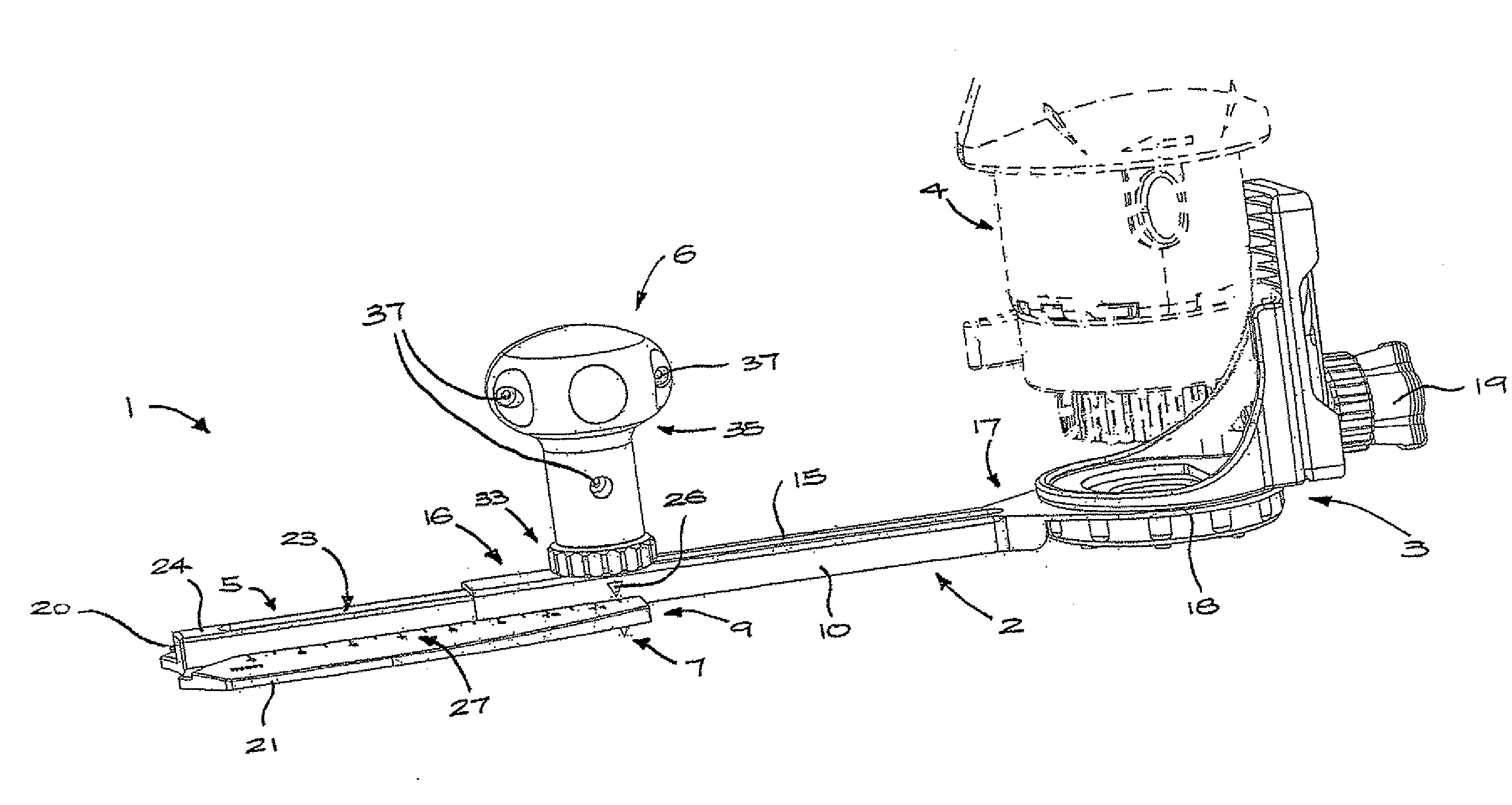
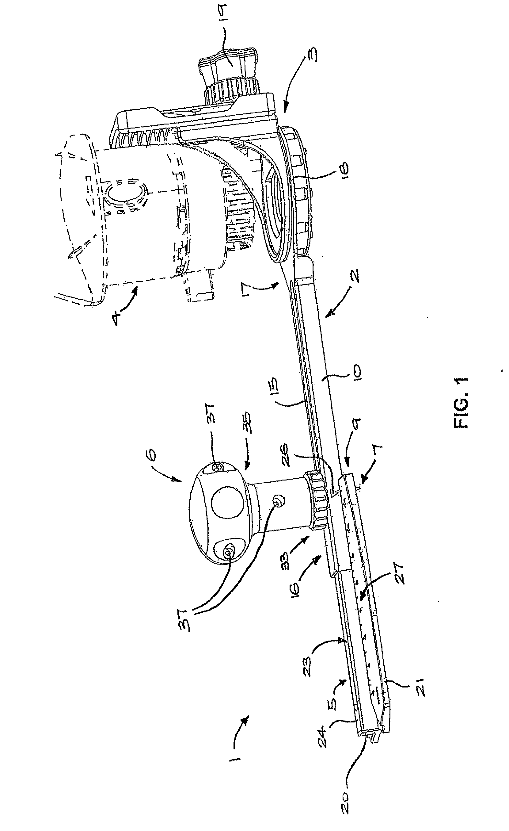
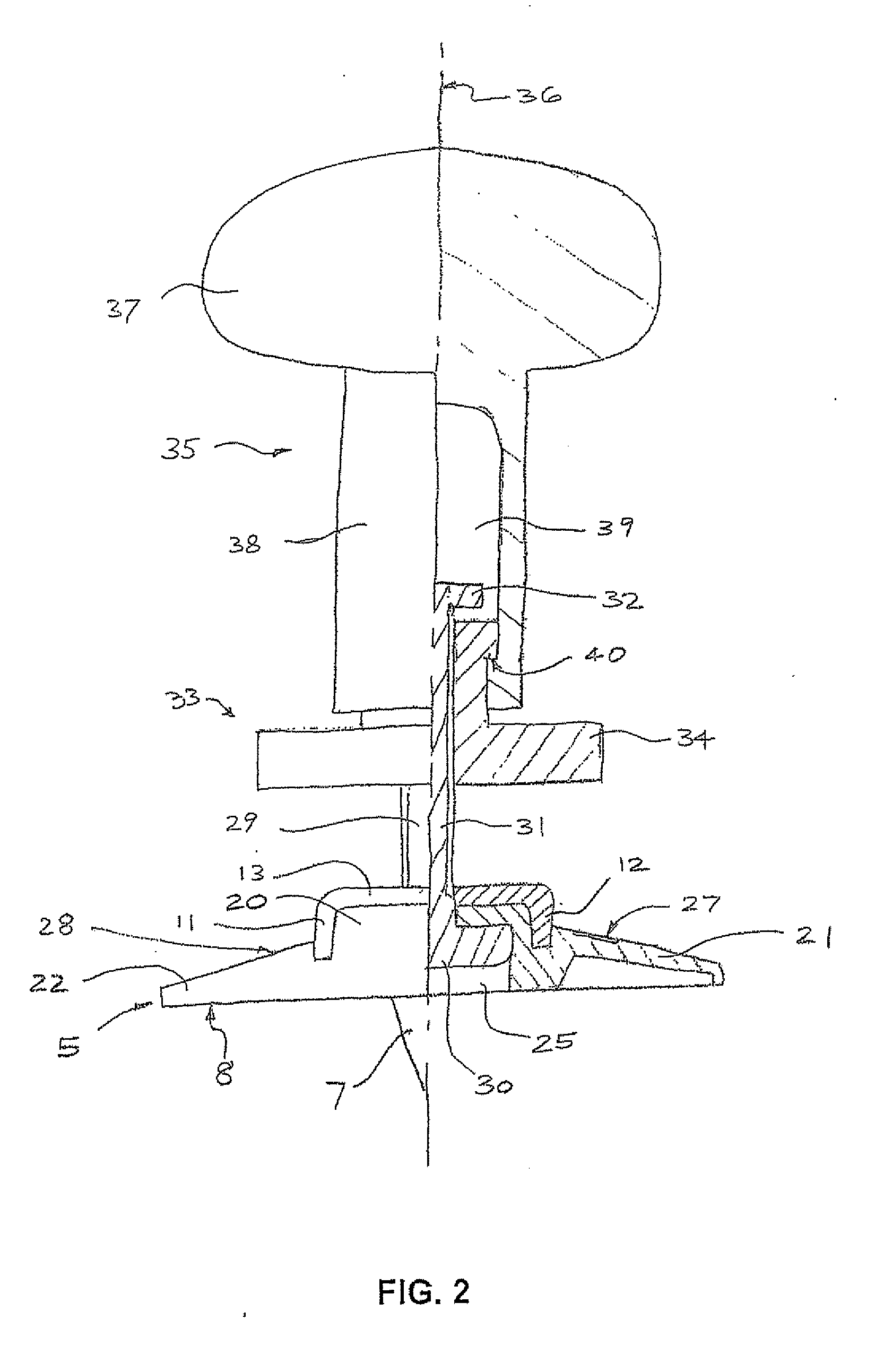
[0029]Referring to the drawings, particularly FIGS. 1 and 2, an arc-cutting guide 1 includes an elongate a swing arm 2 with a fixture 3 at one end for mounting a hand tool, such as the rotary electric cutting tool 4 (shown in dashed outline in FIG. 1). A slider member 5 is telescopically engaged with the swing arm 2 and connected thereto by the handle assembly 6. A point 7 projects from a planar lower face 8 of the slider member 5. The point 7 is offset longitudinally as far as possible from a centre of the slider member, being positioned adjacent to a first end 9 of the slider member 5.

[0030]The swing arm 2 includes a bar portion 10 having a U-shaped section comprising parallel flanges 11, 12 joined by a web 13 to define an inverted channel 14. A longitudinal slot 15 is formed centrally in the web 13, extending from first to a second end 16, 17 of the bar portion 10. At the second end 17 a ring portion 18 is formed integrally with the bar portion 10. The fixture 3 is mounted on the...


PUM

PropertyMeasurementUnit
lengthaaaaaaaaaa
radiusaaaaaaaaaa
radiiaaaaaaaaaa

Abstract

A swing arm has a fixture at one end for mounting a hand tool, and a longitudinally-extending channel including a slot. An elongate slider member is engaged in the channel, and includes a point offset longitudinally from center of the slider member for engagement with a workpiece to define a center about which the swing arm is rotated. A fastener having a head and threaded shank is retained in a recess such that the shank extends through the slot. A threaded knob is engaged with the shank for clamping the slider member in position, and a handle connected to and captively retained with the knob is free to rotate about a handle axis.

Description

TECHNICAL FIELD[0001]The present invention relates to an arc-cutting guide for forming circular and arcuate cuts in a workpiece with a powered hand tool, such as a rotary cutting tool.BACKGROUND OF THE INVENTION[0002]Craftsmen, as well as hobbyists, commonly have a need to cut out large circular or arcuate pieces of wood, carpet and tile, or the like, to make many different products. Numerous arc-cutting guides have been used for guiding cutters for such work. Most of these devices consist of a swing arm with a cutting tool holder of some kind, a point or means for defining a pivot, and possibly a measuring device. By attaching a rotary cutter to a swing arm of known length which is then anchored at a pivot point on a workpiece, the cutter can be moved along a circumferential path to shape the workpiece to the desired radius.[0003]U.S. Pat. No. 6,752,572 describes an arc-cutting guide comprising a swing arm defining a longitudinally extending channel and a slot. A fixture at one end...

Claims


Application Information

Patent Timeline
Patent Type & Authority Applications(United States)
IPC IPC(8): B26D7/00B23Q27/00
CPCB23Q9/0021Y10T409/30644B23Q9/0035Y10T83/863
Inventor FONG, STEVEN SZE CHUNHEUN, PING HAY
Owner CHOON NANG ELECTRICAL APPLIANC
Why Eureka
Try Eureka