Image projecting system, image projecting method, computer program, and recording medium

a projecting system and projector technology, applied in the field of image projecting system and image projecting method, can solve problems such as differences between individual projector apparatuses, and achieve the effects of preventing blanks from appearing in the image projected onto the screen, and uniform luminance of the entire screen

Inactive Publication Date: 2009-08-27
SONY CORP
View PDF3 Cites 14 Cited by
  • Summary
  • Abstract
  • Description
  • Claims
  • Application Information

AI Technical Summary

Benefits of technology

[0036]In this way, since each pixel in the image projected onto the screen is produced by superimposing images projected by a plurality of projector apparatuses, it is possible to keep the luminance of the entire screen uniform.
[0037]According to an embodiment of the present invention, since images projected onto a screen by a plurality of projector apparatuses are superimposed, the luminance of the image on the entire screen is made uniform. Also, even if one or more projector apparatuses breaks down and becomes unable to project an image, other projector apparatuses that are adjacent to the broken projector will continue projecting images, resulting in the effect that it is possible to prevent blanks from appearing in the image projected onto the screen.

Problems solved by technology

(1) Vulnerability to Differences Between Individual Projector Apparatuses

Method used


Image

  • Image projecting system, image projecting method, computer program, and recording medium
  • Image projecting system, image projecting method, computer program, and recording medium
  • Image projecting system, image projecting method, computer program, and recording medium

Examples


first embodiment

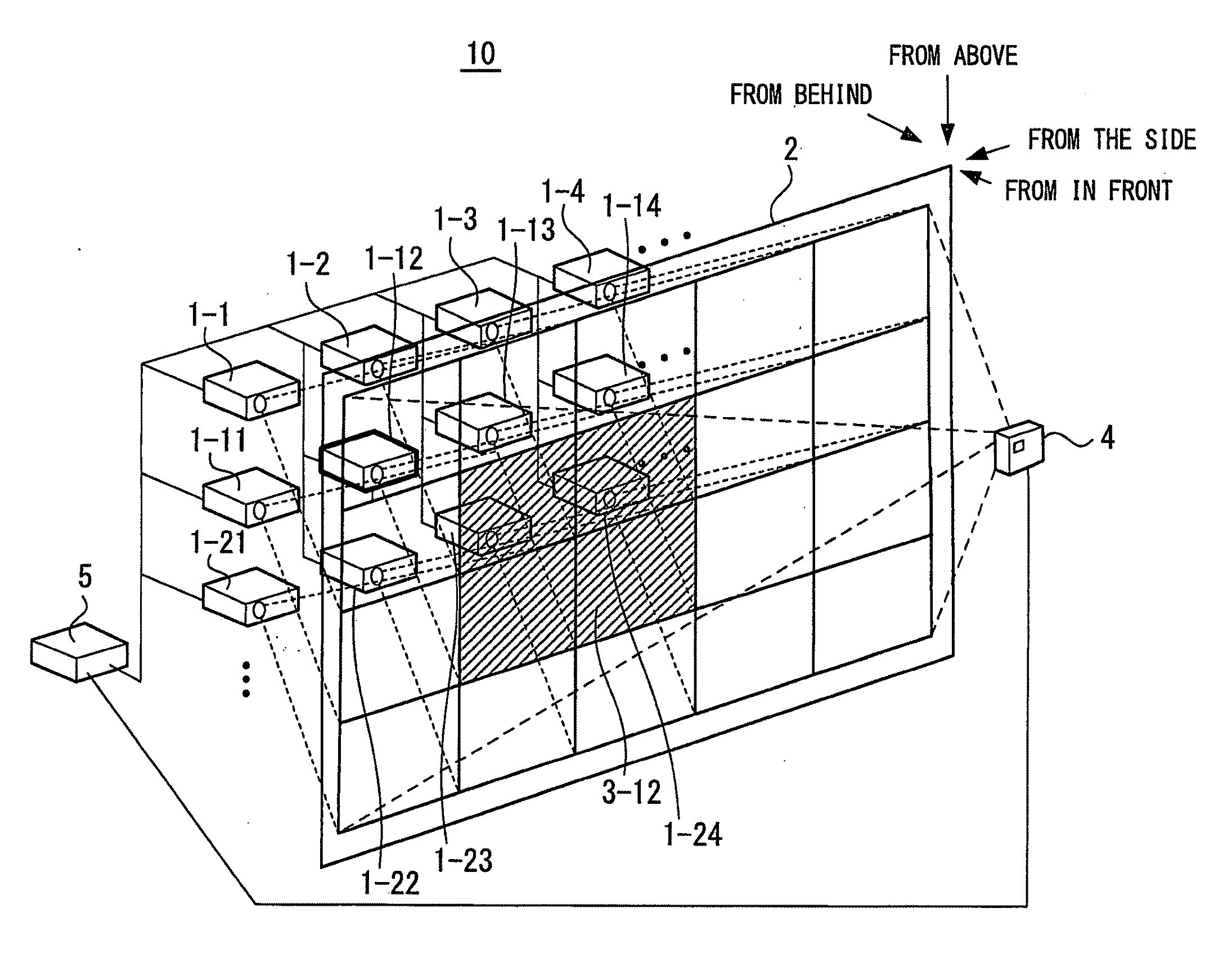
[0074]the present invention will now be described with reference to FIGS. 7 to 27. The present embodiment is described for an example where the present invention is applied to an image projecting system 10 that can display a high-definition image on a screen with uniform luminance by superimposing images projected using a plurality of projector apparatuses.

[0075]FIG. 7 shows an example construction of an image projecting system 10 including a plurality of projector apparatuses. The image projecting system 10 supplies image signals to N projector apparatuses 1-1 to 1-N with the same projection performance. In the present embodiment, the case where N=35 projector apparatuses will be described.

[0076]The image projecting system 10 according to the present embodiment includes the N projector apparatuses, a screen 2 as a display screen for the projected images, an observation unit 4 for observing the image projected onto the screen 2, and a control apparatus 5 that receives information ob...

second embodiment

[0234]As shown in FIGS. 31A to 34D, in the image projecting system 70 the positions (phase pattern) of the images projected by the projector apparatuses change at every moment. The phase in which a pixel position of an input pixel value is present is determined and the delay adjusting unit 21 holds the input signal until the timing at which projected images are projected onto such phase. The image signal is then outputted to the image projecting unit 22 in accordance with such timing. By doing so, it is possible to treat the projector apparatuses as projector apparatuses where the number of pixels in the image projected onto the screen 2 has quadrupled.

[0235]Also, the image projecting system 70 according to the second embodiment described above switches between phase patterns at extremely short intervals (for example, 1 / 60 seconds) for each region (in the present embodiment, ¼ of an image). In this way, by switching between phase patterns, on the time axis, images outputted by four...


PUM


Abstract

An image projecting system is provided. The image projecting system includes a plurality of projector apparatuses, an observation apparatus, and a control apparatus. The projector apparatuses project images based on inputted image signals onto a screen so that the images are displaced relative to one another by a predetermined amount and superimposed. The observation apparatus observes luminance of an image region composed of a plurality of images projected onto the screen by the plurality of projector apparatuses. The control apparatus supplies the plurality of projector apparatuses with the image signals having an adjusted luminance value of each pixel for an image projected by each projector apparatus based on an observation result of the observation apparatus.

Description

CROSS REFERENCES TO RELATED APPLICATIONS[0001]The present invention contains subject matter related to Japanese Patent Application JP 2008-045214 filed in the Japanese Patent Office on Feb. 26, 2008, the entire contents of which being incorporated herein by reference.BACKGROUND OF THE INVENTION[0002]1. Field of the Invention[0003]The present invention relates to an image projecting system and an image projecting method that are suitably applied to projecting images onto a screen using a plurality of projector apparatuses, a computer program applied to a processing method thereof, and to a recording medium that stores such computer program.[0004]2. Description of the Related Art[0005]In the past, to realize a large-screen display that has high resolution, a method of projecting a large image by arranging a plurality of projector apparatuses in a grid has been proposed.[0006]FIG. 1 shows an example construction of an existing image projecting system 100 including a plurality of projec...

Claims


Application Information

Patent Timeline
Patent Type & Authority Applications(United States)
IPC IPC(8): G03B21/14
CPCG03B21/14G03B21/13G03B37/04H04N9/3147H04N9/3182
Inventor KONDO, TETSUJIROMUKAI, HITOSHIIWASAKI, MASANORITANAKA, KENJIKOKUBO, TETSUSHIHIBI, HIROFUMITANAKA, KAZUMASAMORISAKI, HIROYUKI
Owner SONY CORP
Why Eureka
Try Eureka