
Waste liquid collector
- Summary
- Abstract
- Description
- Claims
- Application Information
AI Technical Summary
Benefits of technology
Problems solved by technology
Method used
Image

Examples
first embodiment
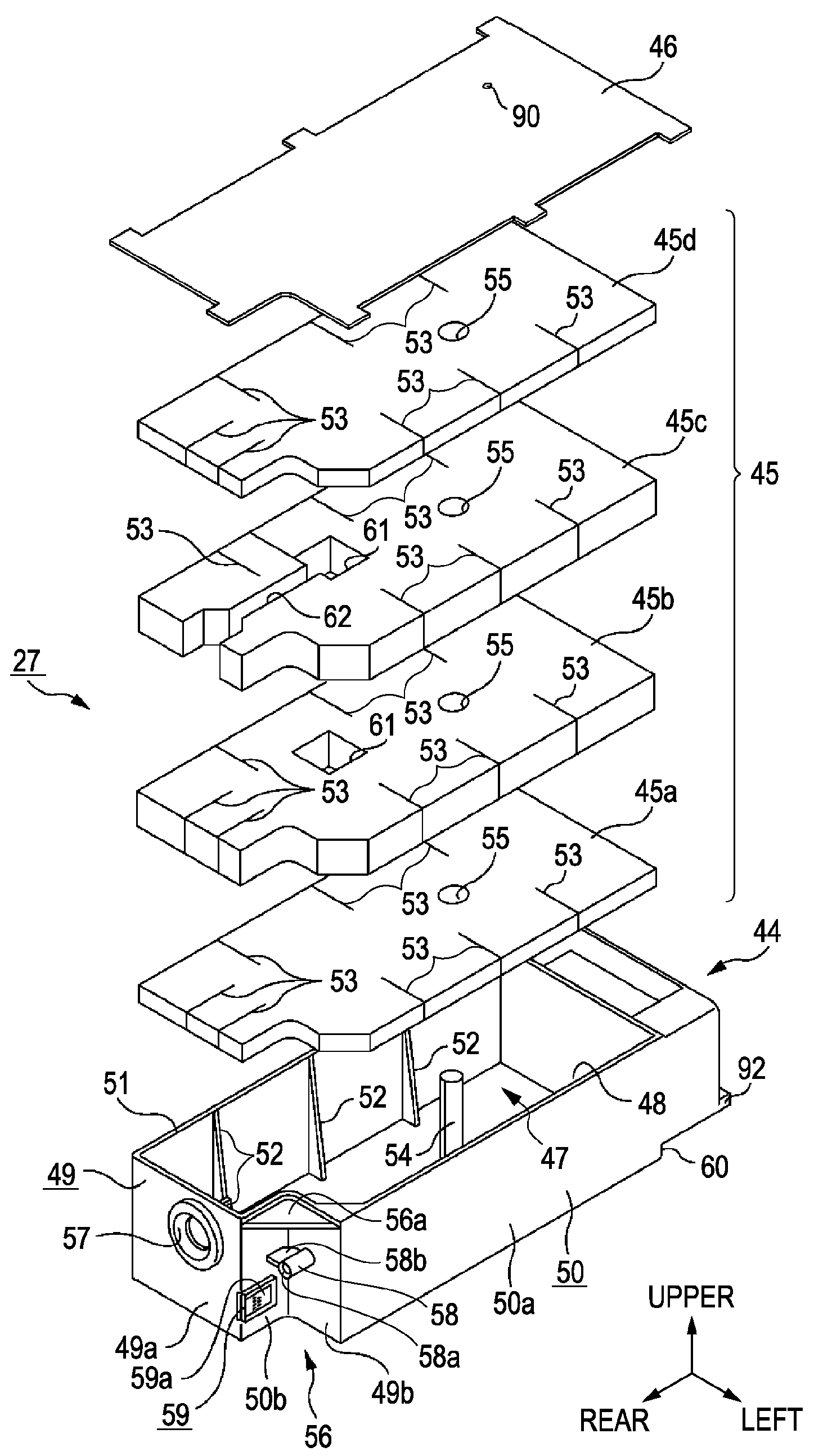
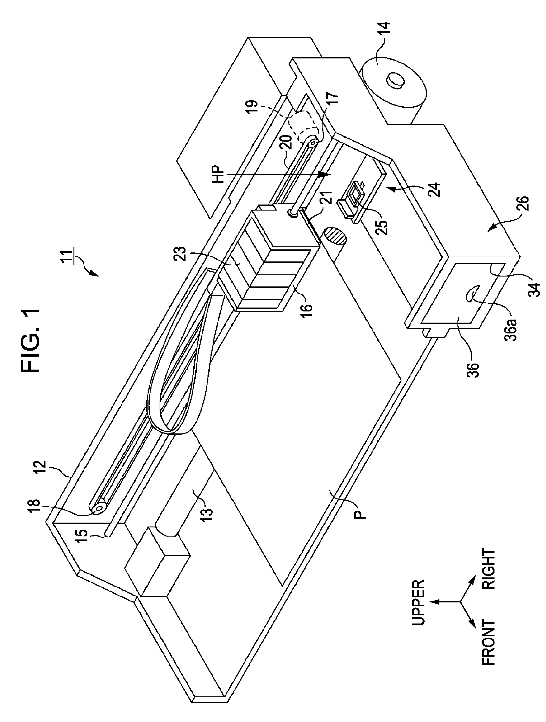
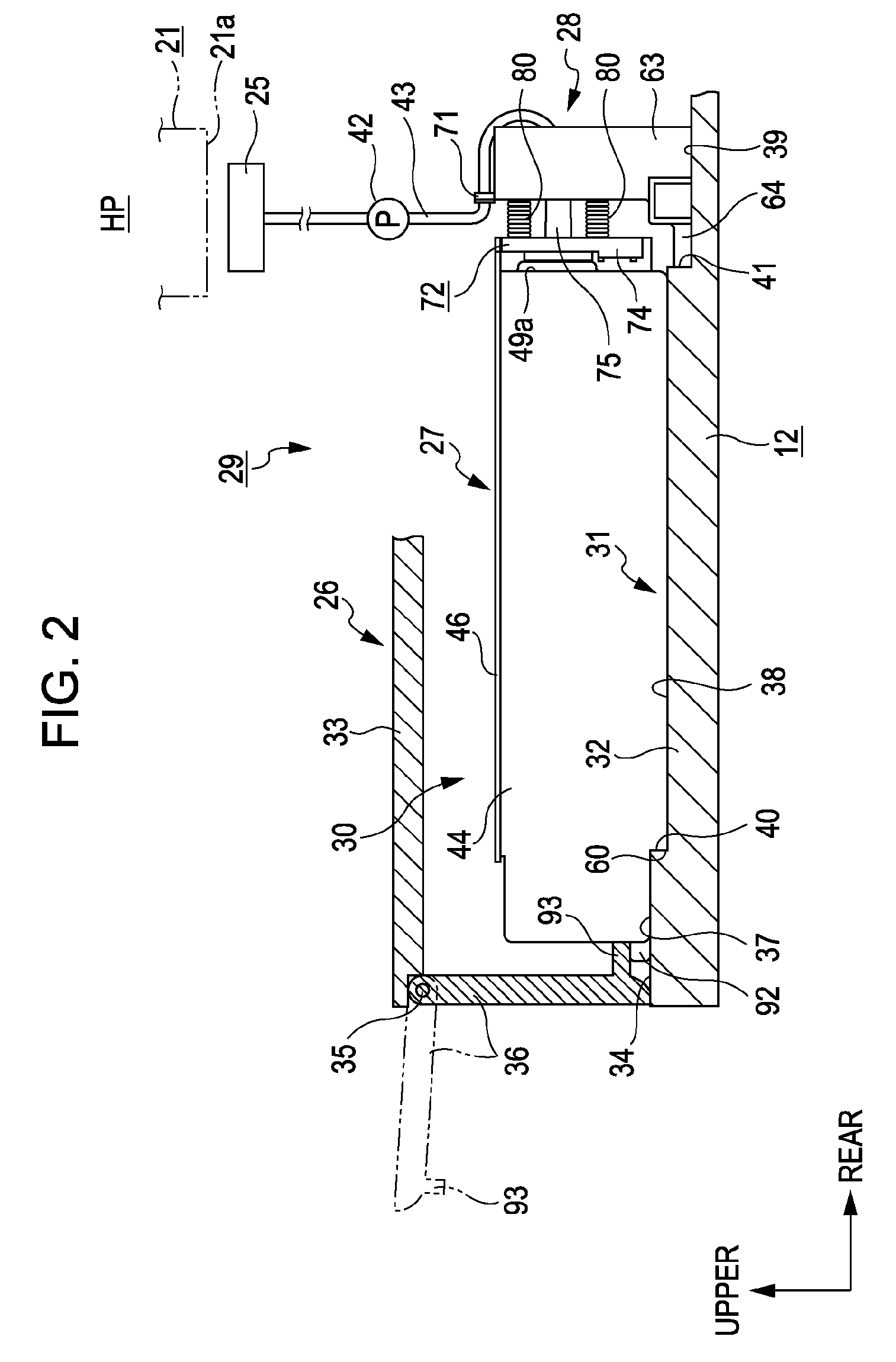
[0061]Hereinafter, an ink jet printer which is an example of a liquid ejecting device including a waste liquid collecting system in which a waste liquid collector according to the invention is detachably mounted will be described with reference to FIGS. 1 to 11 according to a first embodiment. “Front and rear directions”, “upper and lower directions”, and “right and left direction” in the following description refer to “front and rear directions”, “upper and lower directions”, and “right and left direction” indicated by arrows in FIGS. 1 to 3, unless particularly mentioned.
[0062]As shown in FIG. 1, an ink jet printer (hereinafter, referred to as “a printer) 11 as a liquid ejecting device according to this embodiment includes a frame 12 having a rectangular shape in plan view. A platen 13 extends in the right and left direction inside the frame 12. A sheet-feeding mechanism which is disposed above the platen 13 and includes a sheet-feeding motor 14 feeds a print sheet P from the rear...
second embodiment
[0173]Next, a second embodiment of the invention will be described with reference to FIG. 12. In the second embodiment, since only a formation location of the air communication hole 90 is different from that in the first embodiment and the other configuration is the same, the air communication hole 90 will be mainly described below. In addition, the same reference numerals are given to the same constituent elements and repeated description is omitted.
[0174]In the waste ink tank 27 according to this embodiment, as shown in FIG. 12, the air communication hole 90 is formed at the substantially center in the longitudinal direction of the film member 46. In addition, when the discharge unit 97 of the cylindrical body 73 is inserted into the container member 44 from the connection port 57 of the waste ink tank 27, a distance Y between the front end opening 76a and the air communication hole 90 is configured to be shorter than a distance X between the connection port 57 and the front end o...
third embodiment
[0213]Hereinafter, an ink jet printer which is an example of a liquid ejecting device including a waste liquid collecting system in which a waste liquid collector according to the invention is detachably mounted will be described with reference to FIGS. 1 to 11 according to a first embodiment. “Front and rear directions”, “upper and lower directions”, and “right and left direction” in the following description refer to “front and rear directions”, “upper and lower directions”, and “right and left direction” indicated by arrows in FIGS. 1 to 3, unless particularly mentioned.
[0214]As shown in FIG. 1, an ink jet printer (hereinafter, referred to as “a printer) 11 as a liquid ejecting device according to this embodiment includes a frame 12 having a rectangular shape in plan view. A platen 13 extends in the right and left direction inside the frame 12. A sheet-feeding mechanism which is disposed above the platen 13 and includes a sheet-feeding motor 14 feeds a print sheet P from the rear...
PUM
 Abstract
Description
Claims
Application Information