Load port apparatus and method of driving the same

a technology of loading port and auxiliary equipment, which is applied in the direction of electric devices, conveyor parts, transportation and packaging, etc., can solve the problems of reducing operation time and downsizing of apparatus, and achieve the effect of finishing operation in a short tim

Active Publication Date: 2020-05-26
TDK CORPARATION
View PDF8 Cites 0 Cited by
  • Summary
  • Abstract
  • Description
  • Claims
  • Application Information

AI Technical Summary

Benefits of technology

[0007]The present invention has been achieved under such circumstances. It is an object of the invention to provide a load port apparatus capable of appropriately connecting a wafer transportation container with a frame opening by a small mechanism that can operate quickly.
[0043]In the method of driving the load port apparatus according to the present invention, when the wafer transportation container moves to the dock position, the flange groove is disposed closely to the frame, and the small engagement portion can securely be engaged with the wafer transportation container. Moreover, the engagement portion can move in a small movement distance, and the method of driving the load port apparatus can thereby finish operation in a short time. In the method, the engagement portion limits the movement of the wafer transportation container, and an appropriate connection state between the wafer transportation container and the frame opening can thereby be maintained.

Problems solved by technology

In the technique using a pressing arm configured to be engaged with an upper part of a FOUP, a positional displacement of the FOUP is prevented, but the pressing arm is large and moves over a large distance, and there is thereby a problem with downsizing of apparatus.
Since the pressing arm moves over a large distance, the technique needs the time for a positional change of the pressing arm and has a problem with reduction in operation time.

Method used


Image

  • Load port apparatus and method of driving the same
  • Load port apparatus and method of driving the same
  • Load port apparatus and method of driving the same

Examples


Embodiment Construction

[0050]Hereinafter, the present invention is described based on an embodiment shown in the figures.

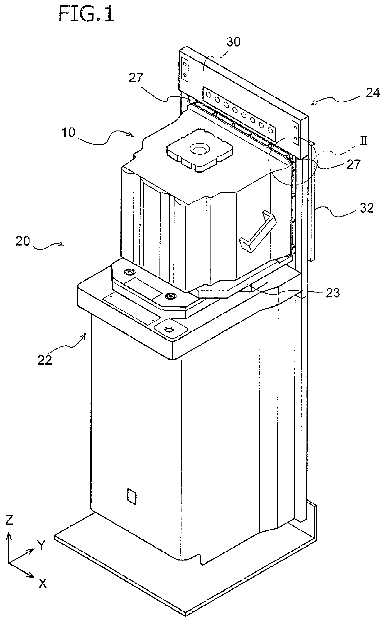
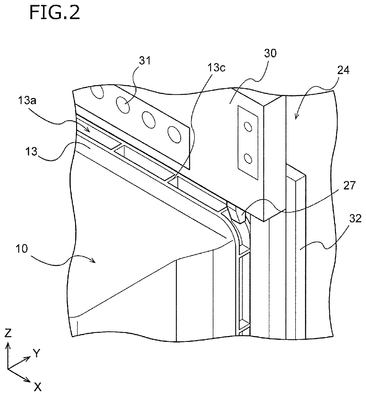
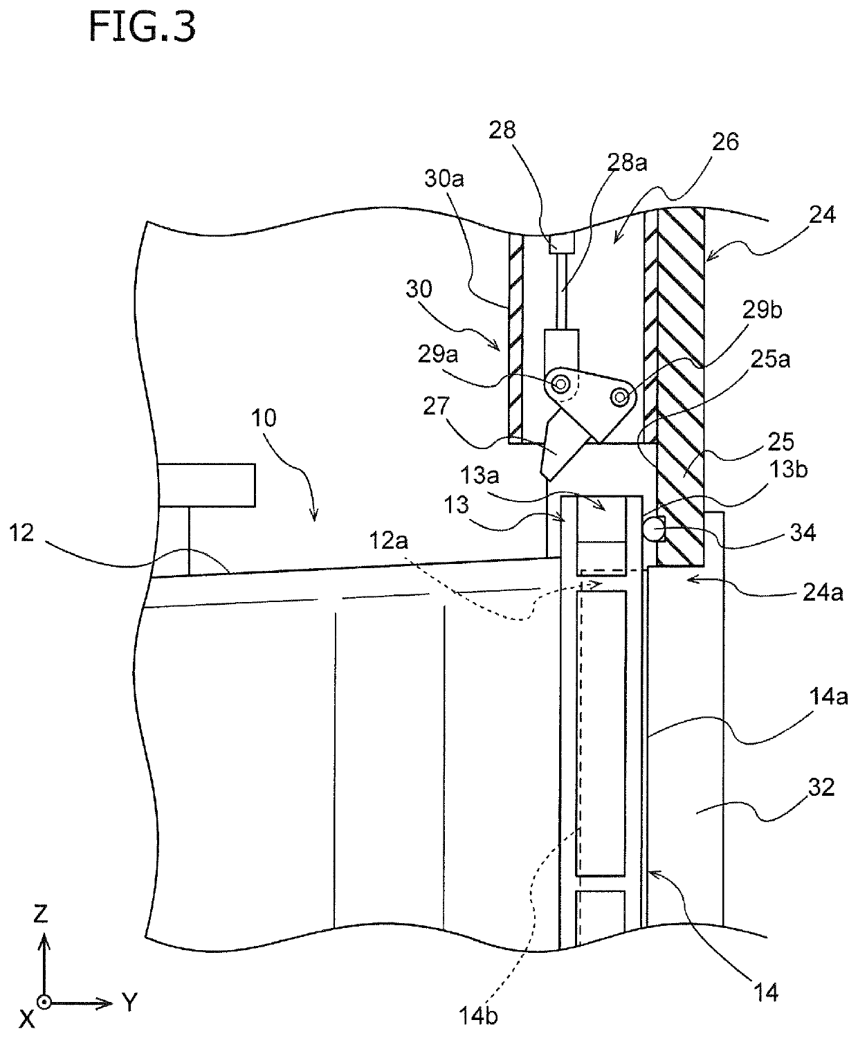
[0051]FIG. 1 is a schematic perspective view of a load port apparatus 20 according to an embodiment of the present invention. For example, the load port apparatus 20 is used as an interface that connects a wafer transportation container 10 with a space where a minienvironment is formed in a semiconductor factory. The load port apparatus 20 is placed so that a frame 24 constitutes a part of side walls forming a minienvironment. The load port apparatus 20 connects a main opening 12a of the wafer transportation container 10 shown in FIG. 1 with a frame opening 24a (see FIG. 3 and FIG. 2).

[0052]As shown in FIG. 1, the load port apparatus 20 includes an installation part 22 having an installation table 23, the frame 24 with the frame opening 24a, a cover portion 30, a door 32, and a flange clamp 26 shown in FIG. 3. Moreover, the load port apparatus 20 includes a bottom clamp part (not shown)...


PUM


Abstract

A load port apparatus connects a main opening of a wafer transportation container with a frame opening. The load port apparatus includes an installation part, a frame, and a flange clamp. The installation part has an installation table configured to install the wafer transportation container and move to and from the frame opening. The frame is upright from the installation part and has the frame opening. The flange clamp includes an engagement portion and a drive portion. The engagement portion is configured to be engaged with a flange surrounding an outer circumference of the main opening. The drive portion is configured to drive the engagement portion. The engagement portion is engaged from above or the side with a flange groove formed in the flange and opening radially outwardly.

Description

BACKGROUND OF THE INVENTION[0001]The present invention relates to a load port apparatus and a method of driving the same.[0002]In a manufacturing process of semiconductors, wafers are transported between processing devices using a wafer transportation container referred to as FOUP, FOSB, etc. The wafer transportation container includes a main opening for taking in and out wafers and a lid for closing the main opening. The wafers in the wafer transportation container are stored in a sealed space by the lid.[0003]When the lid of the wafer transportation container is opened to take out the wafers from the wafer transportation container and introduce a cleaning gas from the main opening of the wafer transportation container thereinto, used is a load port apparatus for connecting the wafer transportation container with a wall opening. When the load port apparatus is used, the internal space of the wafer transportation container can airtightly be connected with another space, such as mini...

Claims


Application Information

Patent Timeline
Patent Type & Authority Patents(United States)
IPC IPC(8): H01L21/677
CPCH01L21/67775H01L21/67772H01L21/6773H01L21/67766H01L21/673
Inventor IWAMOTO, TADAMASAIGARASHI, HIROSHI
Owner TDK CORPARATION
Why Eureka
Try Eureka