Over heating detection and interrupter circuit

a detection circuit and over heating technology, applied in the electrical field, can solve the problems of deterioration between one of the resilient slot connectors and the inserted electrical blade, raising the electrical resistance of the electrical contact therebetween, and affecting the operation of the circui

Inactive Publication Date: 2009-10-08
TECH RES
View PDF16 Cites 74 Cited by
  • Summary
  • Abstract
  • Description
  • Claims
  • Application Information

AI Technical Summary

Benefits of technology

[0015]A specific embodiment of the present invention is shown in the attached drawings. For the purpose of summarizing the invention, the invention comprises an improved over heating detection and interrupter circuit for interrupting electrical power from a power source receptacle upon the detection of an over heating condition of an electrical plug. A heat sensitive device monito...

Problems solved by technology

In many cases, the mechanical and/or electrical contact between one of the resilient slot connectors and the inserted first and second electrical blades deteriorates thus raising the electrical resistance of the electrical contact therebetween.
This deterioration of the mechanical and/or electrical contact between one of the resilient slot connectors and the inserted first and second electrical blades may be caused by a number of reasons.
The deterioration between one of the resilient slot connectors and the inserted electrical blade may be caused by corrosion of either the resilient slot connector and/or the inserted electrical blade.
Furthermore, the deterioration between one of the resilient slot connectors and the inserted electrical blade may be caused by may be caused by a loss of resiliency of the resi...

Method used


Image

  • Over heating detection and interrupter circuit
  • Over heating detection and interrupter circuit
  • Over heating detection and interrupter circuit

Examples


first embodiment

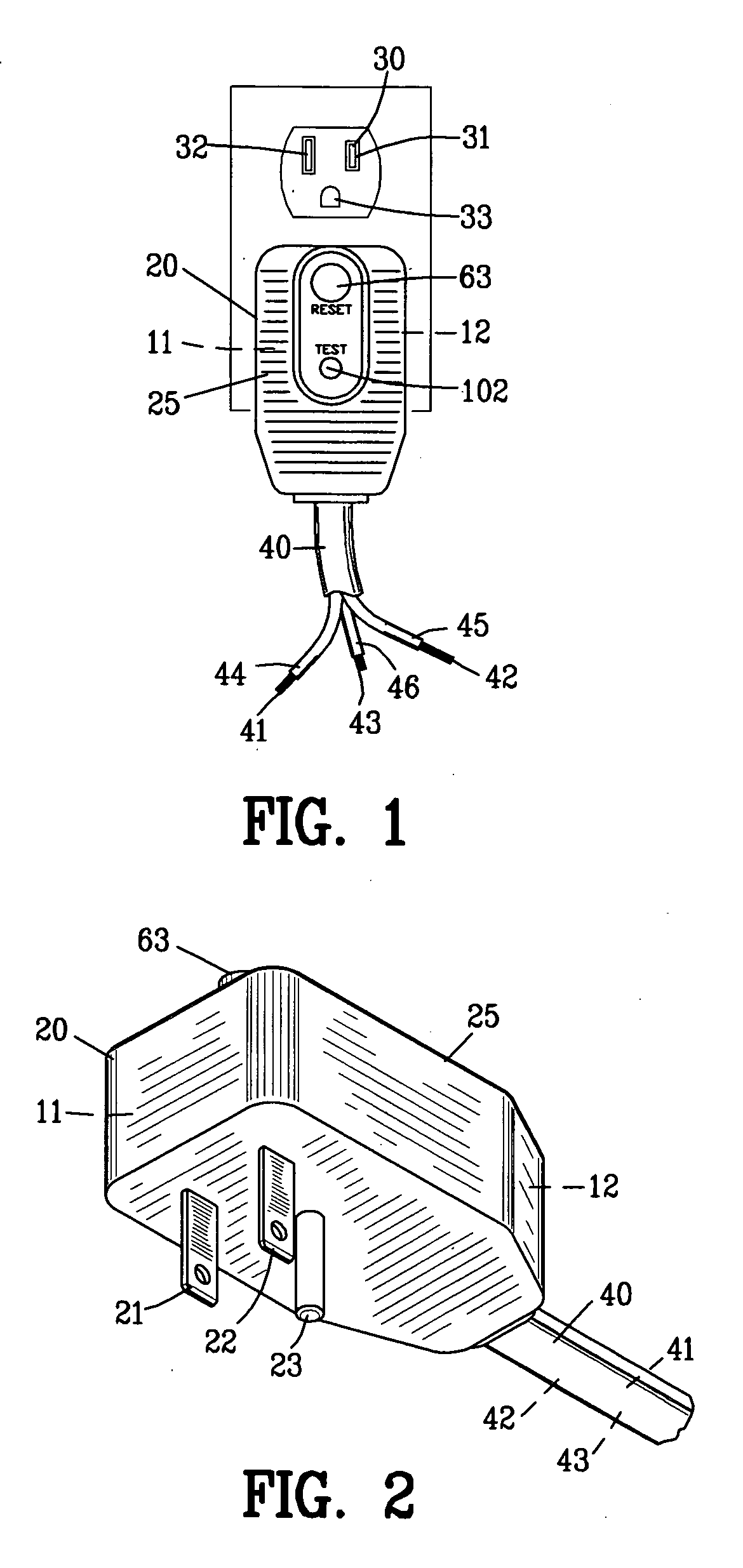
[0068]FIG. 7 is a circuit diagram of the over heating detection circuit 11A and an interrupter circuit 12A. A disconnect switch 50A includes switches 51A and 52A operating in unison. The first and second electrical blades 21A and 22A of the electrical plug 20 shown in FIG. 2 are connected by conductors 26A and 27A to a first side of the switches 51A and 52A. Conductors 41A and 42A of the wire assembly 40A interconnect a second side of switches 51A and 52A to a load 45A. The disconnect switch 50A is shown in the closed or reset condition. The ground lug 23A is connected directly to a ground conductor 43A of the wire assembly 40A bypassing the disconnect switch 50A.

[0069]A diode 71A is connected to the conductor 26A to provide power for the over heating detection circuit 11A and the interruption circuit 12A. The diode 71A provides power through the solenoid coil 60A of the disconnect switch 50A to a conductor 72A. The conductor 72A is connected to a switch shown as a thyristor 73A thr...

second embodiment

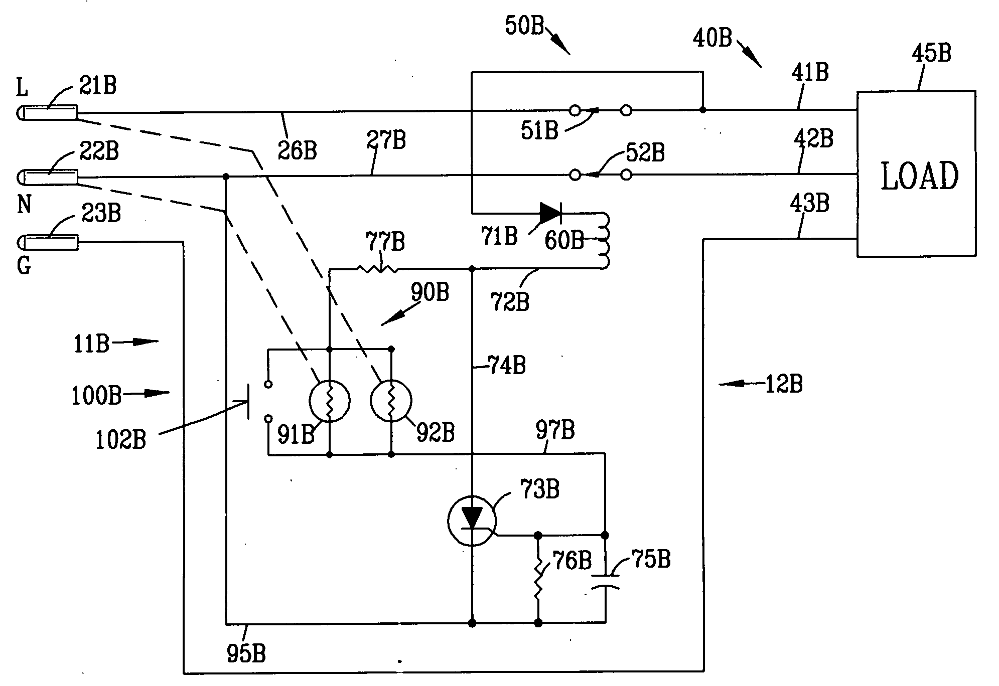
[0077]FIG. 8 is a circuit diagram of the over heating detection circuit 11B and the interrupter circuit 12B. Similar components are labeled with similar reference numerals with the sequential alphabetical character B. A disconnect switch 50B includes switches 51B and 52B operating in unison.

[0078]The first and second electrical blades 21B and 22B are connected by conductors 26B and 27B to a first side of the switches 5B and 52B. Conductors 41B and 42B of the wire assembly 40B interconnect a second side of switches 5B and 52B to a load 45B. The disconnect switch 50B is shown in the closed or reset condition. The ground lug 23B is connected directly to a ground conductor 43B of the wire assembly 40B bypassing the disconnect switch 50B.

[0079]In this second embodiment, the diode 71B is connected to conductor 41B to provide power for the over heating detection circuit 11B and the interruption circuit 12B.

[0080]Under normal operating temperature conditions, the resistance of the first and...

third embodiment

[0082]FIG. 9 is a circuit diagram of the over heating detection circuit 11C and the interrupter circuit 12C. Similar components are labeled with similar reference numerals with the sequential alphabetical character C. A primary circuit 70C is located on the left side of the disconnect switch 50C whereas a secondary circuit 80C is located on the right side of the disconnect switch 50C. The disconnect switch 50C comprises a first, a second and a third switch 51C-53C operating in unison.

[0083]A diode 71C is connected to the conductor 26C of the primary circuit 70C to provide power for the interruption circuit 12C. The diode 71C provides power through the solenoid coil 60C of the disconnect switch 50C to a conductor 72C. The conductor 72C is connected to a switch shown as a thyristor 73C through a conductor 74C. A capacitor 75C and a resistor 76C are connected in parallel at the gate of the thyristor 73C. A resistor 77C is connected through a conductor 78C to a resistor 93C. A capacitor...


PUM


Abstract

An over heating detection circuit and an interrupter circuit are disclosed for interrupting electrical power from a power source receptacle to a load upon the detection of an over heating condition of an electrical plug. A heat sensitive device monitors the temperature of the electrical plug. The over heating detection circuit is connected to the heat sensitive device for detecting an over heated condition in the electrical plug. The interruption circuit includes a disconnect switch connected to the over heating detection circuit for disconnecting electrical power upon the detection of the over heated condition in the electrical plug.

Description

BACKGROUND OF THE INVENTION[0001]1. Field of the Invention[0002]This invention relates to electricity and more particularly to an over heating detection circuit for disconnecting electrical power upon the detection of the over heated condition in an electrical plug.[0003]2. Background of the Invention[0004]The most common method of connecting an electrical appliance to an electric power source is through the use of an electrical power plug inserted into an electrical power source receptacle. The electrical power plug includes a first and a second electrical blade for insertion within a first and a second slot of the power source receptacle. The first and second electrical blades are retained within the first and second slots of the electrical power source receptacle by a resilient slot connector located within the first and second slots of the electrical power source receptacle. The resilient slot connectors located within the first and second slot provides a mechanical engagement b...

Claims


Application Information

Patent Timeline
IPC IPC(8): H02H5/04H02H3/00H02H3/08
CPCH01R13/6683H02H5/042H01R2103/00H01R24/28
Inventor BRUGNER, FRANK S.WILLIAMS, THOMAS S.
Owner TECH RES
Why Eureka
Try Eureka