Linear incendiary strand and method for prescribed fire ignition

a fire ignition and incendiary strand technology, applied in the direction of explosives, coatings, weapons, etc., can solve the problems of insufficient sustained flame generation, intense, momentary flame, etc., and achieve the effect of improving the control and manipulation of fire behavior and ensuring the safety of burn personnel

Active Publication Date: 2009-11-05
ARCTOS RES
View PDF23 Cites 8 Cited by
  • Summary
  • Abstract
  • Description
  • Claims
  • Application Information

AI Technical Summary

Benefits of technology

[0024]In accordance with yet another aspect of the invention, the method of igniting fires using a linear incendiary strand pr

Problems solved by technology

These devices provide an intense, momentary flame rapidly along their lengths, but they d

Method used


Image

  • Linear incendiary strand and method for prescribed fire ignition
  • Linear incendiary strand and method for prescribed fire ignition
  • Linear incendiary strand and method for prescribed fire ignition

Examples


example no.1

EXAMPLE NO. 1

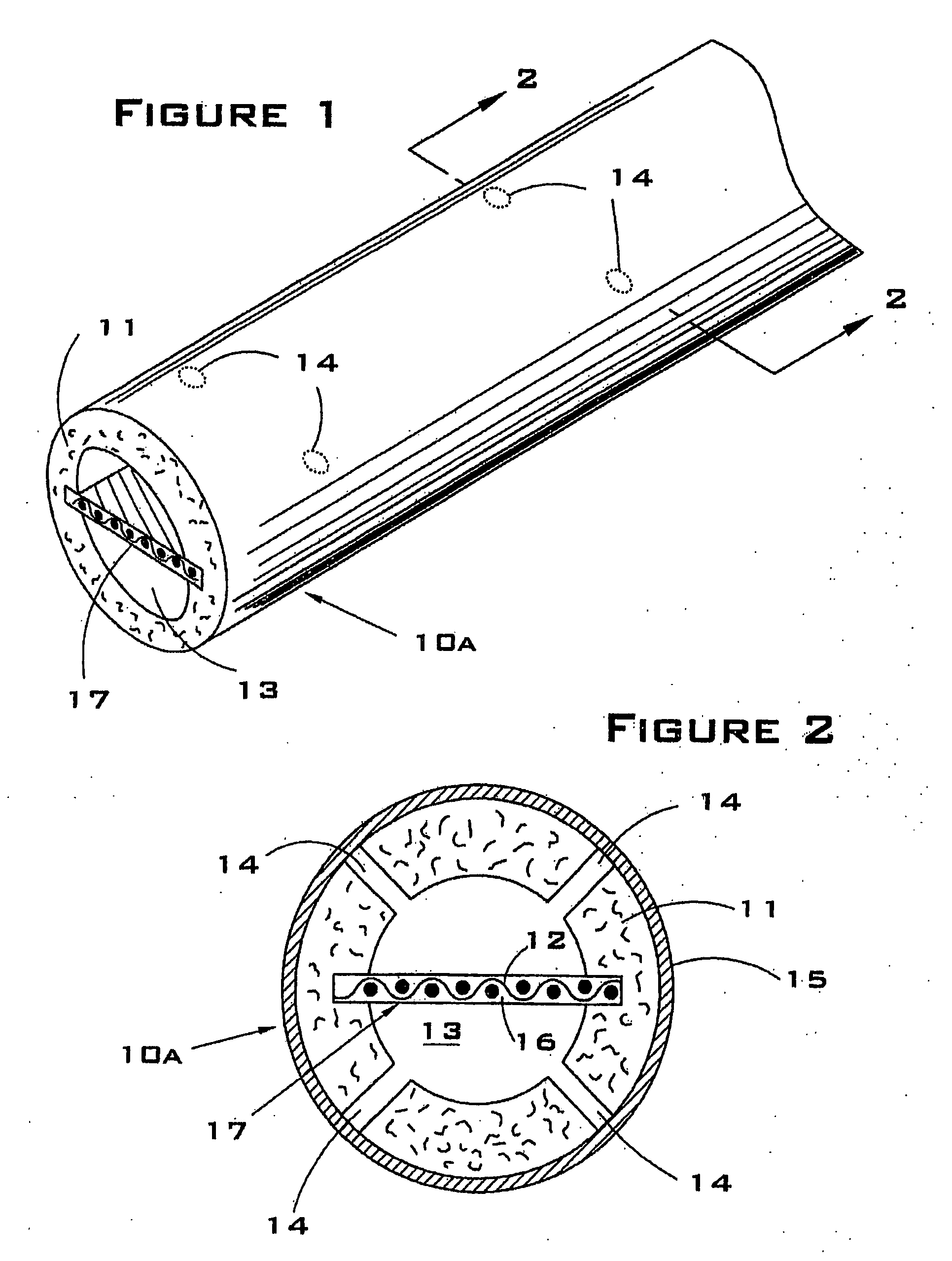
[0047]Referring now to FIG. 1 and FIG. 2, a specific embodiment of the present invention is shown as having the physical form of an elongate cord-like structure of indeterminate length. FIG. 1 illustrates a fragmentary isometric view of a linear incendiary strand; FIG. 2 shows a cross-sectional view of the same strand taken along line 2-2 of FIG. 1. The incendiary strand 10a has a tubular body formed of a resinous fuel composition 11; the outside diameter of such strand is preferably about ¾ inch (1.9 cm). The central longitudinal duct of strand 10a forms a gas channel 13, having an inside diameter of about ¼ inch (0.64 cm). Pyrotechnic element 17, comprised of fabric substrate 12 with a coating of pyrotechnic composition 16, is disposed centrally within gas channel 13, with its lateral edges fixedly embedded in fuel composition 11 along the longitudinal axis of strand 10a. A plurality of vent passages 14 are radially disposed about the circumference of strand 10a to fo...

example no.2

EXAMPLE NO. 2

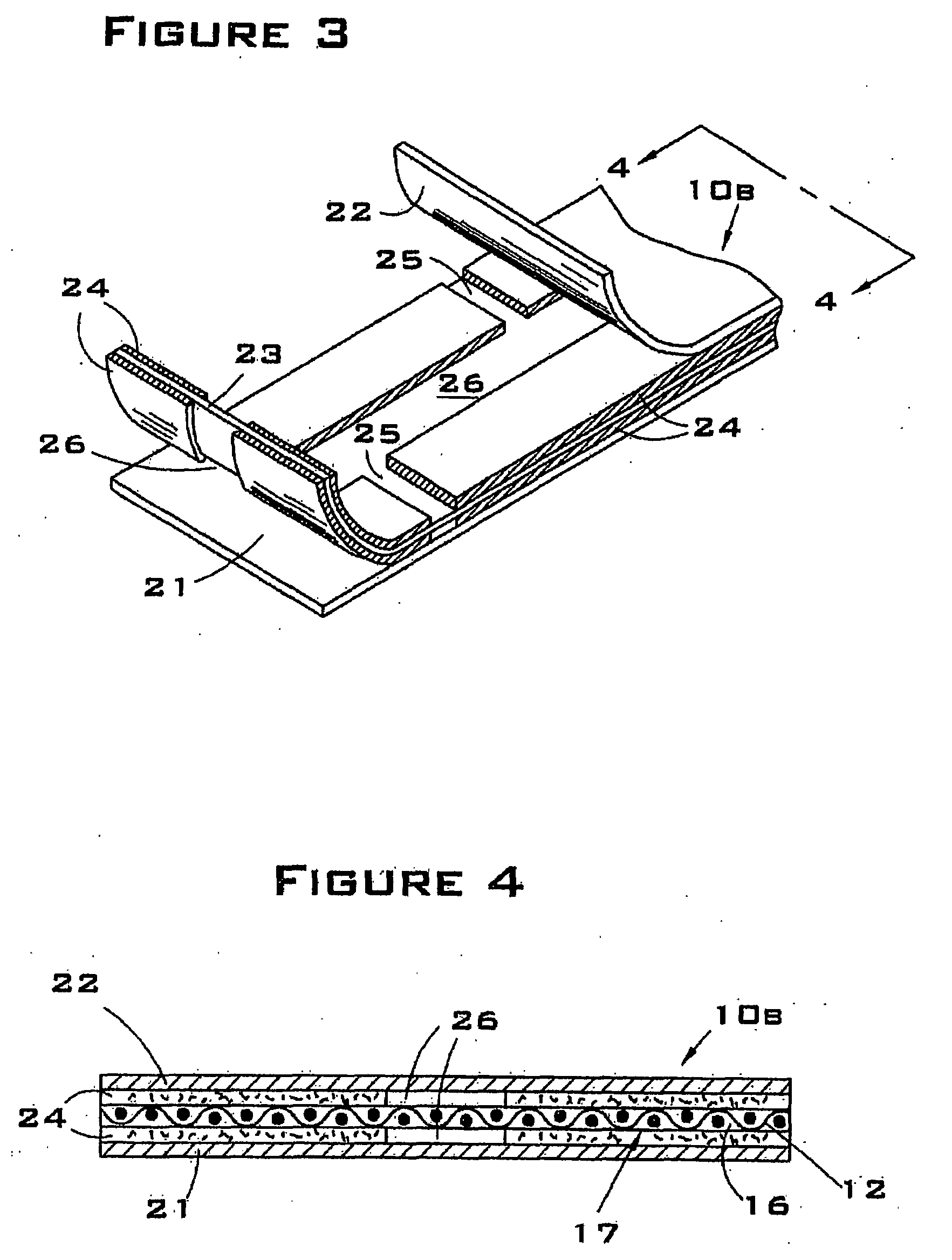
[0056]In an alternative embodiment, the incendiary device of the present invention is shown in FIG. 3 and FIG. 4 as having the physical form of a wide tape, or ribbon, of indeterminate length. FIG. 3 illustrates a fragmentary isometric view of a linear incendiary strand 10b of such structure, herein referred to as an incendiary tape; FIG. 4 shows a cross-sectional view of the same strand, taken along line 4-4 of FIG. 3. The incendiary tape 10b is produced as a lamination of multiple layers, comprising upper covering layer 22, lower covering layer 21, fuel composition 24 and pyrotechnic element 23. Fuel composition 24 is present in a discontinuous pattern on both upper and lower surfaces of pyrotechnic element 23, forming central longitudinal gas channel 26 in connective arrangement with multiple lateral gas channels 25. Lateral gas channels 25 are open to the exterior lateral edges of tape 10b, and are longitudinally offset to either side of longitudinal gas channel 26....

example no.3

EXAMPLE NO. 3

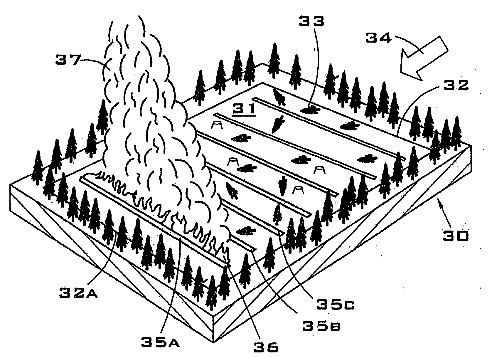
[0065]The ignition method of the present invention is suitably adapted for use in conducting a type of controlled burn that is known in the art as High Energy or Mass Ignition burning. This type of burning may be used to mitigate air pollution concerns by creating a fire of high enough intensity to generate strong convective transport of smoke vertically, resulting in the dilution and dispersion of particulate emissions from a fire. (Ottmar et. al., 2001). In addition, it may also be desirable to generate sufficient heat energy over the fire to enable the smoke column to reach the lifting condensation level of the atmosphere, where cloud scavenging of smoke may substantially reduce particulate levels (Radke et al., 1991). A fire-generated convection column that has a greater measure of vertical kinetic energy than that presented horizontally by atmospheric winds will tend to rise directly upward for a distance above the fire, allowing gasses and embers to cool. A weak s...


PUM


Abstract

An elongate, flexible, incendiary device for producing a nearly instantaneous source of flaming combustion along a linear pathway of indeterminate length. The incendiary device is provided in the form of a solid, continuous strand, such as, for example, a ribbon, tape, cord, filament, rope or tube. The device is comprised of means for rapid ignition along the longitudinal axis of the strand in co-linear arrangement with a solid or semi-solid combustible fuel composition. Upon ignition, the device produces flames from its exterior surface for a duration of time suitable for igniting nearby combustible matter. The incendiary device provides a nearly instantaneous line of fire for igniting prescribed fires, controlled burns, and backfires. A method for igniting vegetative matter over an area of land using one or more indeterminate lengths of a rapidly igniting linear incendiary strand.

Description

CROSS-REFERENCE TO RELATED APPLICATION[0001]This application claims priority back to U.S. Application No. 60 / 542,377, which was filed on 6 Feb. 2004.STATEMENT REGARDING FEDERALLY SPONSORED RESEARCH OR DEVELOPMENT[0002]This invention is based upon work supported by the Cooperative State Research, Education, and Extension Service, U.S. Department of Agriculture, under Grant No. 2003-33610-13068. The federal government has certain rights in the invention.BACKGROUND OF THE INVENTION[0003]1. Field of the Invention[0004]This invention relates to incendiary devices and methods used to initiate fires, more specifically, for the purpose of igniting prescribed fires in forest and range land vegetation.[0005]2. Description of the Related Art[0006]Prescribed burning refers to the deliberate application of fire to wildlands to achieve specific resource management objectives. It involves the tasks of planning, igniting and controlling the fire. Known fire behavior models are used to determine the...

Claims


Application Information

Patent Timeline
IPC IPC(8): F42B12/44B05D3/12C06B21/00F42D1/04
CPCC06B45/00F42D1/04F42B12/44C06C5/04
Inventor REISTROFFER, JEFFREY P.
Owner ARCTOS RES
Why Eureka
Try Eureka