Buckling restrained brace

Active Publication Date: 2010-01-14
NAT APPLIED RES LAB
View PDF4 Cites 27 Cited by
  • Summary
  • Abstract
  • Description
  • Claims
  • Application Information

AI Technical Summary

Benefits of technology

[0018]Due to the presence of the grooves, the buckling restrained brace can be connected easily to the connecting plates.
[0019]Furthermore, since the supporting plate portions are perpend

Problems solved by technology

Such connecting process is time-consuming.
However, the dual-tub

Method used


Image

  • Buckling restrained brace
  • Buckling restrained brace
  • Buckling restrained brace

Examples


Example

[0050]Before the present invention is described in greater detail in connection with the preferred embodiments, it should be noted that similar elements and structures are designated by like reference numerals throughout the entire disclosure.

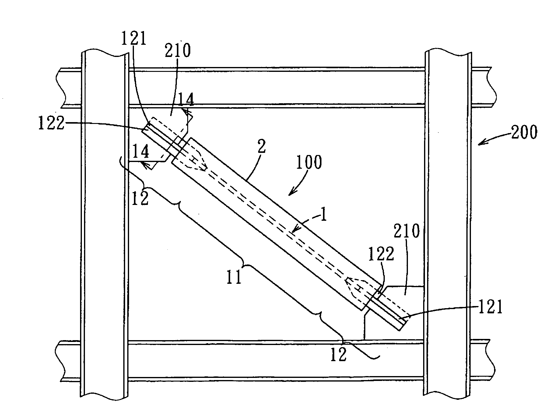
[0051]Referring to FIGS. 10, 11, 12, and 13, the buckling restrained brace 100 is connected fixedly between two connecting plates 210 of a steel framework 200 of a building, and includes an axial member 1 and a restraining unit 2.

[0052]The axial member 1 extends along an axial direction (A), and has a middle section 11 and two coupling sections 12 extending respectively and integrally from two opposite ends of the middle section 11. The middle section 11 has an elongated plate body 111. Each coupling section 12 has a supporting plate portion 121 coplanar with the elongated plate body 111, and two contacting plate portions 122 extending respectively from two opposite side surfaces of the supporting plate portion 121 along a first transverse dire...


PUM


Abstract

A buckling restrained brace includes an axial member and a restraining unit. The axial member extends along an axial direction, and has two coupling sections for connecting respectively to two connecting plates of a framework of a building, and a middle section connected between the coupling sections. Each coupling section has a supplying plate portion coplanar with an elongated plate body of the middle section, and a contacting plate portion extending perpendicularly from the supporting plate portion. An outer end of the supplying plate portion of each coupling section has a groove formed therethrough along a transverse direction of the axial member, extending along the axial direction, and permitting a respective one of the connecting plates to engage fittingly therewith and contact the corresponding contacting plate portion.

Description

CROSS-REFERENCE TO RELATED APPLICATION[0001]This application claims priority of Taiwanese Application No. 097125878, filed on Jul. 9, 2008.BACKGROUND OF THE INVENTION[0002]1. Field of the Invention[0003]This invention relates to a buckling restrained brace, and more particularly to a buckling restrained brace that is formed with grooves for engaging respectively connecting plates of a framework of a building.[0004]2. Description of the Related Art[0005]Buckling restrained braces are used in a steel framework of a building for absorbing vibration energy generated by an earthquake, to delay the damage of the framework resulting from the shock of the earthquake, and to break prior to breakage of the parts of the framework coupled to the buckling restrained braces. In general, current buckling restrained braces can be classified into the following three types:[0006]1. Single-tube and single-core type. Referring to FIGS. 1 and 2, a single-tube and single-core type buckling restrained bra...

Claims


Application Information

Patent Timeline
IPC IPC(8): E04B1/98
CPCE04H9/028E04H9/02E04H9/0237E04H9/021E04H9/025
Inventor TSAI, KEH-CHYUANWEI, CHIH-YU
Owner NAT APPLIED RES LAB
Why Eureka
Try Eureka