Illumination apparatus, display apparatus, and electronic device

Active Publication Date: 2013-01-31
138 EAST LCD ADVANCEMENTS LTD
View PDF8 Cites 7 Cited by
  • Summary
  • Abstract
  • Description
  • Claims
  • Application Information

AI Technical Summary

Benefits of technology

[0009]It is an advantage of some aspects of the invention to provide an illumination apparatus having a large illumination area and in which connector members can easily be connected to each other even in the case where the connector me

Problems solved by technology

However, even when a connector member is used, when flexible wiring extends from the light source substrate as per the configuration disclosed in JP-A-2007-279480, a large load is applied to the light source substrate via the wiring during assembly, which results in the risk of the light source substrate deforming.
If such deformation occurs, the optical axes of the light-emitting elements will tilt, which is undesirable.
However, with the configuration shown in FIG. 10, to avoid interference between the light guiding plate 1080 and the connector members 1071 and 1076, it is necessary to provide a cutout 1809 in the light guiding plate 1080, which

Method used


Image

  • Illumination apparatus, display apparatus, and electronic device
  • Illumination apparatus, display apparatus, and electronic device
  • Illumination apparatus, display apparatus, and electronic device

Examples


Example

First Embodiment

Overall Configuration

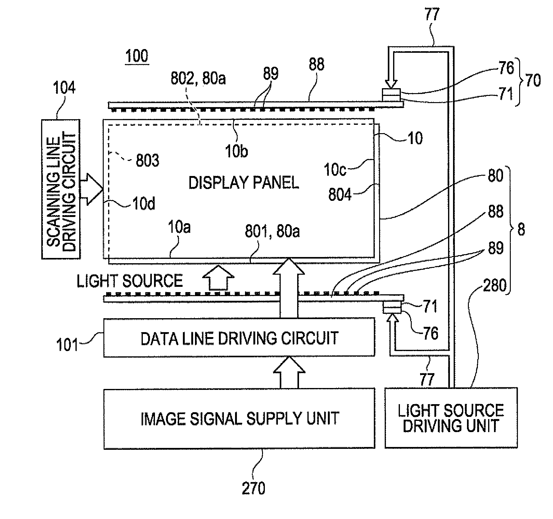
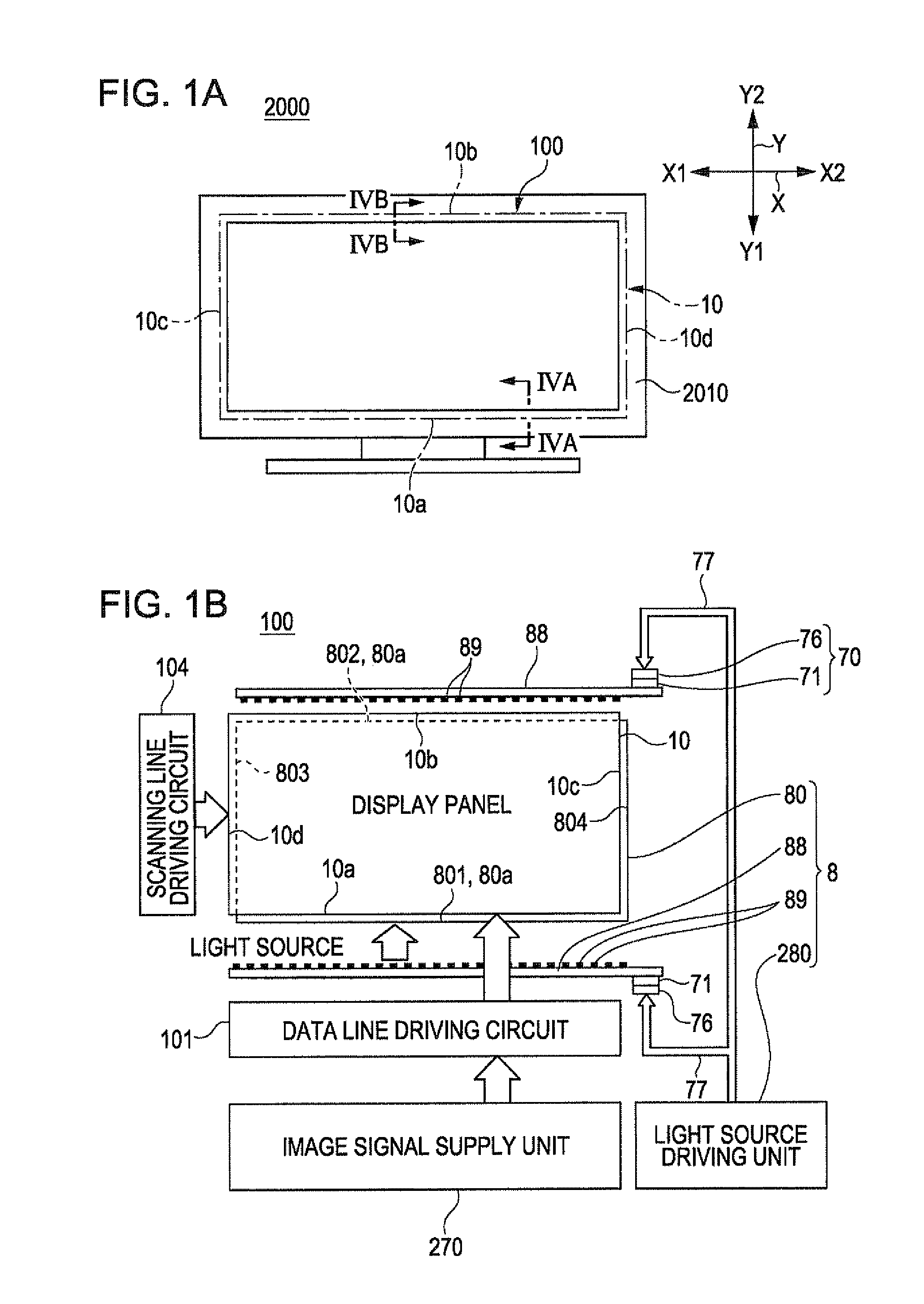
[0032]FIGS. 1A and 13 are schematic diagrams illustrating an LCD television (electronic device) provided with a display apparatus according to a first embodiment of the invention, where FIG. 1A is a schematic diagram illustrating the LCD television from the exterior thereof, and FIG. 1B is a block diagram illustrating the electrical configuration of the display apparatus.

[0033]An electronic device 2000 shown in FIG. 1A is an LCD television, and includes a display apparatus 100, a television frame 2010, and so on. As shown in FIG. 1B, the display apparatus 100 includes a display panel 10 (a liquid-crystal panel), which will be mentioned later with reference to FIGS. 2A, 2B, and so on, an image signal supply unit 270 that supplies image signals to the display panel 10, and an illumination apparatus 8 that supplies illumination light to the display panel 10. In addition, the display apparatus 100 includes a scanning line driving circuit 104 that dri...

Example

Second Embodiment

[0063]FIG. 7 is a schematic diagram illustrating, from above, the configuration of the main elements of the illumination apparatus 8 used in the display apparatus 100 according to a second embodiment of the invention. Note that the basic configuration in this embodiment is the same as that in the first embodiment, and thus corresponding constituent elements will be given the same reference numerals, and descriptions thereof will be omitted.

[0064]Although a single connector member 71 is provided for the light source substrate 88 in the first embodiment, a plurality of connector members 71 may be provided at locations that are distanced in the lengthwise direction of the light source substrate 88. For example, with the illumination apparatus 8 illustrated in FIG. 7, connector members 71 are provided at both ends of the light source substrate 88. In other words, in this embodiment, the connector members 71 are held on the other surface 882 side of the light source subs...

Example

Third Embodiment

[0065]FIGS. 8A and 8B are schematic diagrams illustrating the configuration in the vicinity of the light source substrate 88 used in the illumination apparatus 8 of the display apparatus 100 according to a third embodiment of the invention; FIG. 8A is a diagram schematically illustrating the light source substrate 88 from one surface 881, whereas FIG. 8B is a diagram schematically illustrating the light source substrate 88 from the another surface 882. Note that the configurations of the light-emitting elements 89, light source substrates 88, and so on disposed on the two side-end surfaces 801 and 802 (the light-entry portions 80a) that oppose each other in the Y-axis direction of the light guiding plate 80 are the same. Accordingly, FIG. 8A illustrates the light-emitting elements 89, the light source substrate 88, and so on disposed on the side-end surface 802 of the light guiding plate 80, whereas FIG. 8B illustrates the light-emitting elements 89, the light source...


PUM


Abstract

An illumination apparatus includes: a light guiding plate; a plurality of light-emitting elements disposed along a side-end surface of the light guiding plate that serves as a light-entry portion, each of the plurality of light-emitting elements having a light-emitting surface facing toward the side-end surface; a light source substrate that extends along the light-entry portion and has the plurality of light-emitting elements disposed thereon on one surface side that faces the light-entry portion; and a connector member, held on another surface side of the light source substrate that opposes the one surface side, for supplying power to the plurality of light-emitting elements.

Description

BACKGROUND[0001]1. Technical Field[0002]The present invention relates to illumination apparatuses provided with light guiding plates and light-emitting elements, display apparatuses provided with such illumination apparatuses, and electronic devices provided with such display apparatuses.[0003]2. Related Art[0004]Of the various types of display apparatuses, liquid-crystal apparatuses include an illumination apparatus referred to as a “light guiding plate apparatus” and a transmissive or partially-transmissive display panel (liquid-crystal panel) disposed on top of the illumination apparatus in an overlapping manner on the side of the light-emitting surface thereof; in the illumination apparatus, a plurality of light-emitting elements are provided along the side-end surfaces of the light guiding plate that function as light-entry portions. In the illumination apparatus, a light source substrate is provided along the light-entry portion of the light guiding plate, and a plurality of l...

Claims


Application Information

Patent Timeline
IPC IPC(8): G09F13/18F21V8/00
CPCG02B6/0068G02B6/0073G02B6/009G02B6/0085G02B6/0083
Inventor URANO, NOBUTAKAMOMOSE, YOICHI
Owner 138 EAST LCD ADVANCEMENTS LTD
Why Eureka
Try Eureka