
Mobile Communication Terminal, Mode Switching Method, and Network Switching Method

Active Publication Date: 2009-10-01
KYOCERA CORP
View PDF10 Cites 8 Cited by
  • Summary
  • Abstract
  • Description
  • Claims
  • Application Information

AI Technical Summary

Benefits of technology

[0008]The present invention has been accomplished to solve the above-described problems, and an object of the present invention is to provide a mobile communication terminal capable of easily switching between connectable networks.

Problems solved by technology

However, even when the conventional information processing device is applied to a mobile phone that can also be used as an IP phone, the following problem arises.
The problem is that in the case where the user of the mobile phone does not want it to function as an IP phone, displaying a telephone number assigned to the IP phone results in a display of unnecessary information.
In particular, since mobile phones are small and limited in size for the display screens, unnecessary information is preferably not displayed.
Additionally, there is the problem that for the protocols for establishing a communication by connecting mobile phones to wireless LANs, the protocols are standardized in the lower layers of the OSI layer model, but in the upper layers, the protocols may vary for a plurality of kinds of wireless LANs.

Method used


Image

  • Mobile Communication Terminal, Mode Switching Method, and Network Switching Method
  • Mobile Communication Terminal, Mode Switching Method, and Network Switching Method
  • Mobile Communication Terminal, Mode Switching Method, and Network Switching Method

Examples


first embodiment

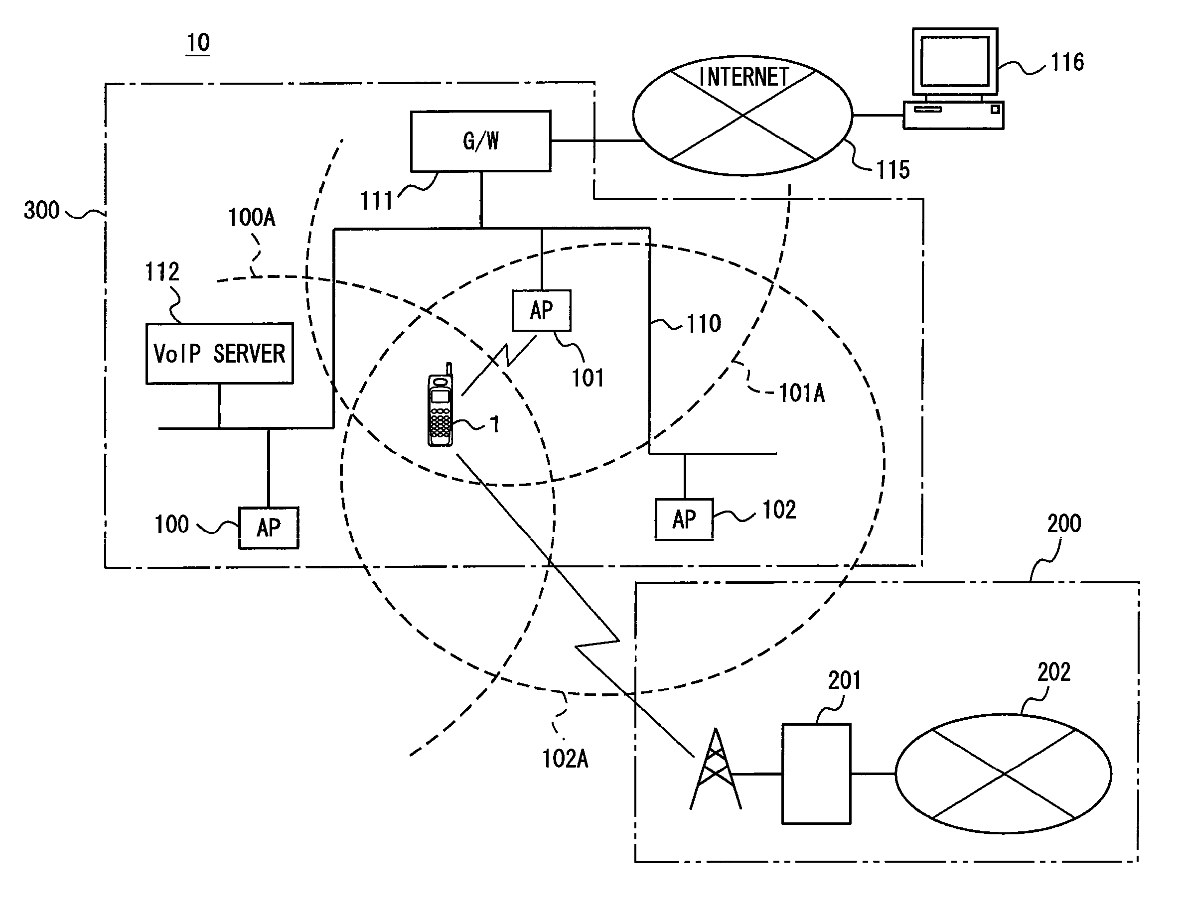
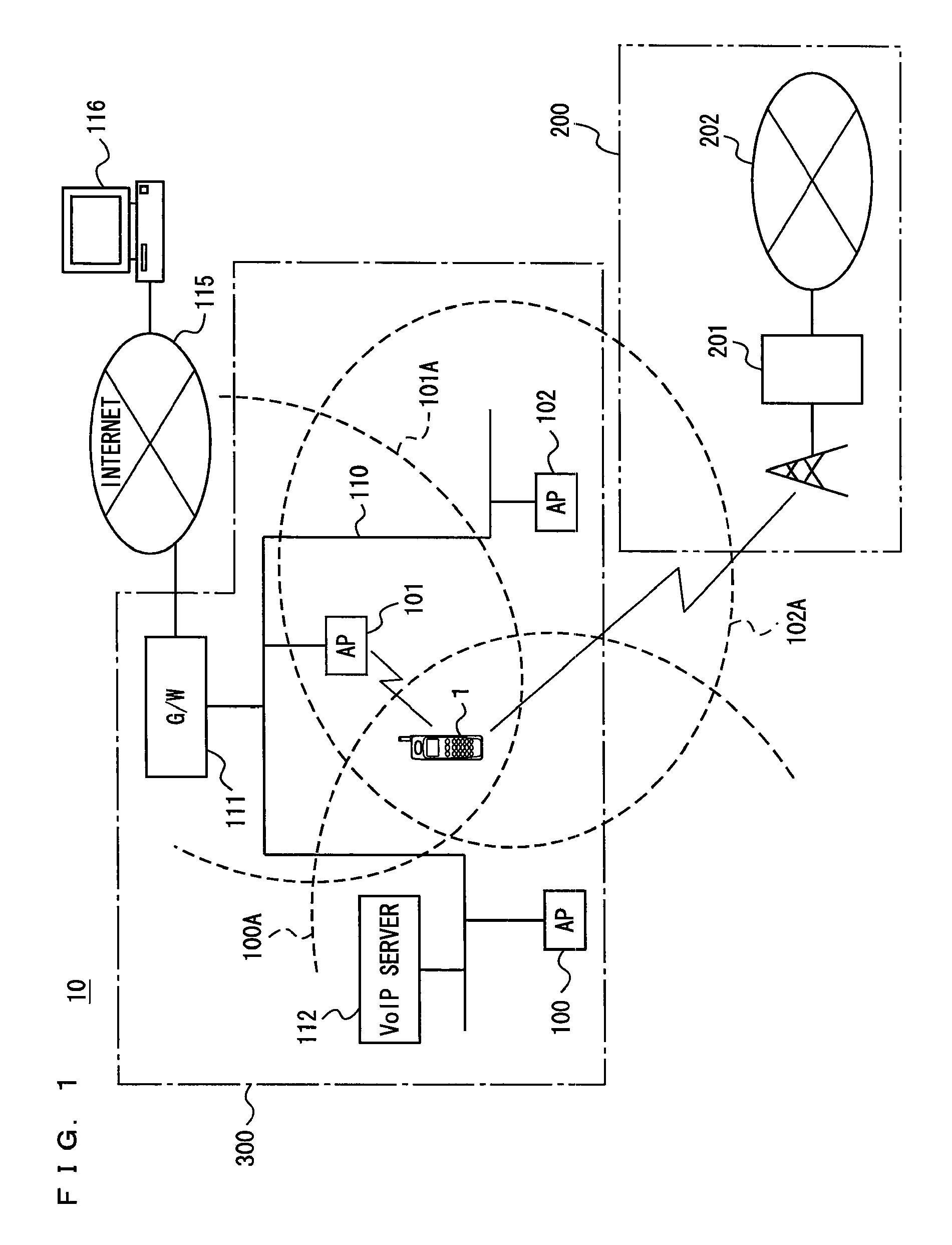
[0058]FIG. 1 is a diagram schematically showing a communication system according to this embodiment. Referring to FIG. 1, a communication system 10 includes a mobile phone system 200 and a wireless LAN system 300. Mobile phone system 200 is a system provided by a telephone service provider, and the example here includes a communication network 202, a base station apparatus 201 connected to communication network 202, and a mobile phone 1 that carries out wireless communication with base station apparatus 201. While the description here is made with one base station apparatus 201, the number of base station apparatuses 201 is not limited. Base station apparatus 201 is a wireless station apparatus that functions as a repeater for communication network 202. Mobile phone 1, when located in a communicable area of base station apparatus 201, carries out wireless communication with base station apparatus 201 in order to be connected to communication network 202. Communication network 202, w...

second embodiment

[0114]Communication system 10 according to a second embodiment differs from communication system 10 according to the first embodiment in that communication system 10 according to the second embodiment includes a plurality of second networks. Description will be made mainly of respects in which communication system 10 according to the second embodiment differs from communication system 10 according to the first embodiment.

[0115]Communication system 10 according to the second embodiment has a similar structure to that of wireless LAN system 300 and includes a different kind of wireless LAN system with a different communication protocol. For example, when wireless LAN system 300 is assumed to be a first LAN established in a company, there may be a case where a second LAN is established in a household. While the case where the first LAN and the second LAN exist as the second networks is exemplified here, the number of the wireless LANs is not limited to two insofar as a plurality of wir...


PUM


Abstract

In order to input / output only necessary information in accordance with the form of application, a mobile phone includes: a wireless circuit 22 to connect to a first network in order to communicate with a device connected to the first network; a wireless LAN circuit 23 to connect to a second network different from the first network in order to communicate with a device connected to the second network; and a setting mode switching portion 21 to switch between a first setting mode capable of activating wireless circuit 22 and wireless LAN circuit 23 and a second setting mode capable of activating only wireless circuit 22 among wireless circuit 22 and wireless LAN circuit 23.

Description

TECHNICAL FIELD[0001]The present invention relates to a mobile communication terminal, a mode switching method, and a network switching method, and more particularly to a mobile communication terminal connectable to wireless LANs and a mode switching method and a network switching method that are executed in the mobile communication terminal.BACKGROUND ART[0002]In recent years, local area networks utilizing wireless communication (hereinafter referred to as “wireless LANs”) have become popular, and it is possible to use wireless communication terminals connected to wireless LANs as IP (Internet Protocol) telephones. Conventional mobile phones are each provided with a communication function that makes a telephone call or the like by making a wireless connection to a network provided by a telephone service provider, and in addition to this communication function, it is possible to install a function that establishes a communication by making a wireless connection to a wireless LAN and...

Claims


Application Information

Patent Timeline
IPC IPC(8): H04W40/00H04M1/724H04W88/06
CPCH04M1/0214H04M1/274508H04W88/06H04M2250/06H04M1/72519H04M1/27453H04M1/724H04B1/40H04W48/18
Inventor OSHIME, HARUYOSHI
Owner KYOCERA CORP
Learn More