Two stage surge protection for single wire multi switch transceiver

a multi-switch transceiver and surge protection technology, applied in the field of signal communication, can solve problems such as harmonics on shared rf cables, short 2.3 mhz tone, and 2.3 mhz swm failur

a multi-switch transceiver and surge protection technology, applied in the field of signal communication, can solve problems such as harmonics on shared rf cables, short 2.3 mhz tone, and 2.3 mhz swm failur

US20100053836A1Inactive Publication Date: 2010-03-04THOMSON LICENSING SA

Image

  • Two stage surge protection for single wire multi switch transceiver
  • Two stage surge protection for single wire multi switch transceiver
  • Two stage surge protection for single wire multi switch transceiver

Examples


Embodiment Construction

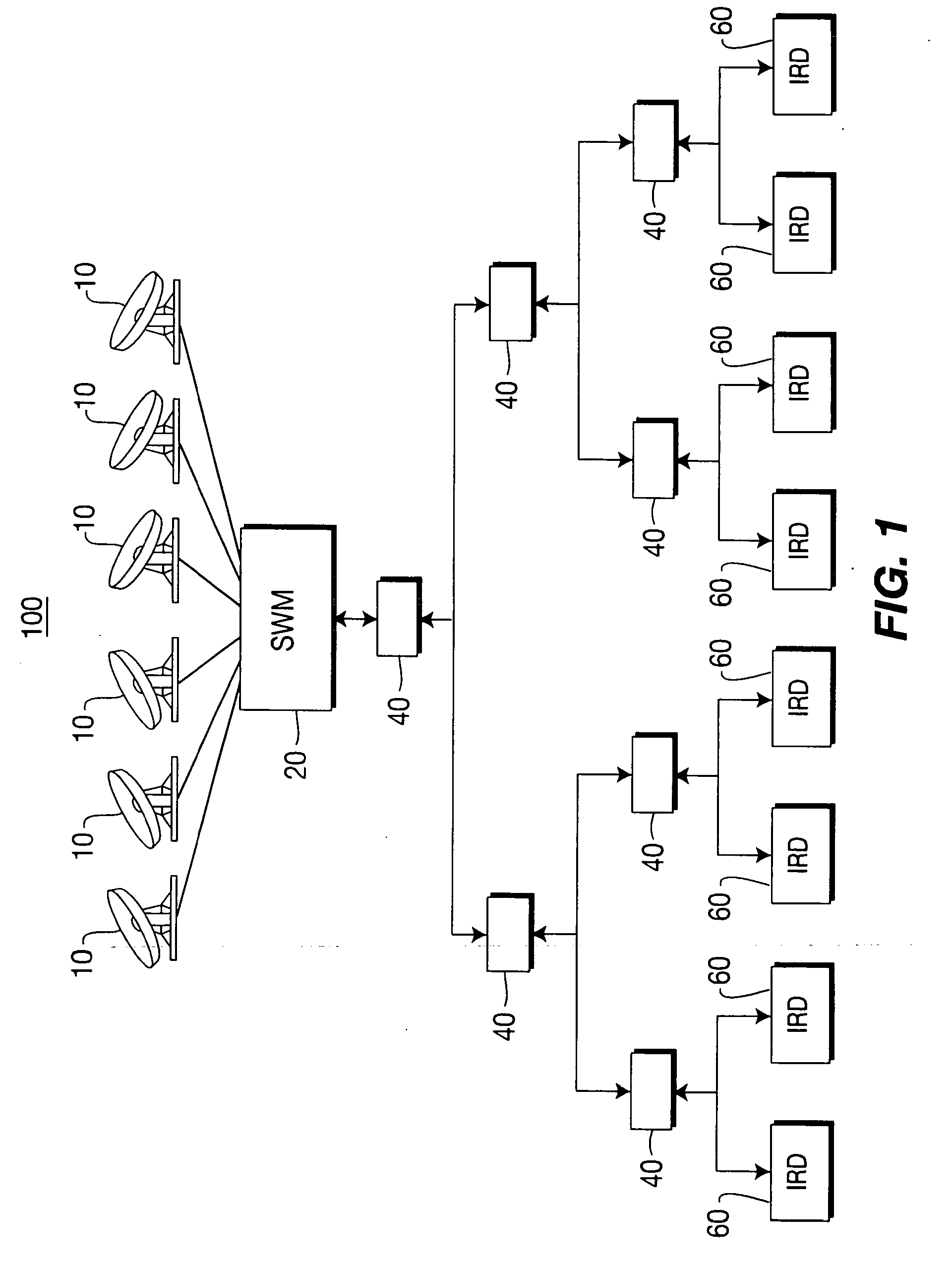
[0024]Referring now to the drawings, and more particularly to FIG. 1, a diagram of an exemplary environment 100 for implementing the present invention is shown. Environment 100 of FIG. 1 comprises a plurality of signal receiving means such as signal receiving elements 10, such as antennas or portions of an antenna or transmission line inputs or low noise block amplifier any other means for receiving an information bearing signal, frequency translating means such as SWM 20, a plurality of signal splitting means such as signal splitters 40, and a plurality of signal receiving and decoding means such as IRDs 60. The signal receiving elements 10 may be operative to shift the frequency of received signals to frequencies more conducive to transmission via transmission lines such as coaxial cables. For example, a low noise block amplifier used in satellite television signal reception may be operative to frequency shift the received signal from around 12 GHz o 1 GHz, or from “Ka” band to “L...


PUM


Abstract

An architecture for protecting circuitry used for signal communications between a frequency translation module (20) and a decoder (60) from transient voltage surges. According to an exemplary embodiment, the apparatus comprises a first signal path between a transmission line and a first reference potential, comprising a high impedance negative surge path; and a second signal path between the transmission line and the first reference potential, comprising a high impedance positive surge path, a low inductance surge path and a DC blocker circuit, wherein said high impedance positive surge path is configured in series with said low inductance surge path and said DC blocker circuit, wherein each of said low inductance surge path and said DC blocker circuit are coupled between said high impedance positive surge path and said source of reference potential.

Description

RELATED APPLICATION[0001]This application claims the benefit of U.S. Provisional Application No. 60 / 920,055 filed Mar. 26, 2007, which is hereby incorporated by reference.BACKGROUND OF THE INVENTION[0002]1. Field of the Invention[0003]The present invention generally relates to signal communications, and more particularly, to architecture for integrating and protecting a single wire multi switch (SWM) transceiver and the legacy LNB mode into the same satellite set top box.[0004]2. Background Information[0005]In a satellite broadcast system, one or more satellites receive signals including audio and / or video signals from one or more earth-based transmitters. The satellite(s) amplify and rebroadcast these signals to signal receiving equipment at the dwellings of consumers via transponders that operate at specified frequencies and have prescribed bandwidths. Such a system includes an uplink transmitting portion (i.e., earth to satellite(s)), an earth-orbiting satellite receiving and tra...

Claims


Application Information

Patent Timeline
04 Mar 2010
Publication
US20100053836A1
IPC
H02H9/04
CPC
H01Q1/247; H01Q1/50; H03F1/52; H03F3/189; H04H40/90; H03J3/24; H03H2/008; H03H3/06
Inventors
XIU, LINCHENG; FITZPATRICK, JOHN JAMES