Pad structure

Inactive Publication Date: 2010-03-18
MICRO-STAR INTERNATIONAL
View PDF4 Cites 13 Cited by
  • Summary
  • Abstract
  • Description
  • Claims
  • Application Information

AI Technical Summary

Benefits of technology

[0009]The skidproof piece is lifted to leave the plane when the casing of the electronic device is slanted, while the slide piece contacts with the plane simultaneously, such that the casing of the electronic device may move on the plane by the slide piece. Theref

Problems solved by technology

However, in certain cases, for example, when a salesman shows data to a customer, the retarding force provided by the pads becomes a burden, such that the user has to uplift the whole laptop computer from the desktop, and turn it to show the content on the screen to the customer.
Therefore, in the entire process of showing data, the need of frequent turning causes much inconvenience in use, and the inner operation devices, such as Central Processing Unit (CPU), are easily to be damaged due to the

Method used


Image

  • Pad structure
  • Pad structure
  • Pad structure

Examples


Example

[0021]The housing of an electronic device referred in the present invention is, for example, a housing of a common electronic device such as a computer, a host, and a screen, and the examples above are for the purpose of illustration only, instead of limitation.

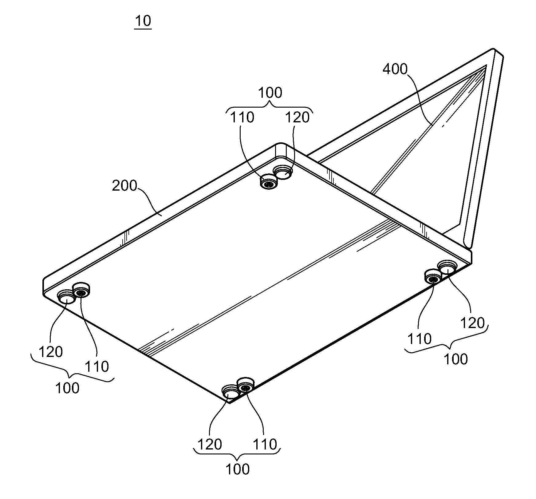
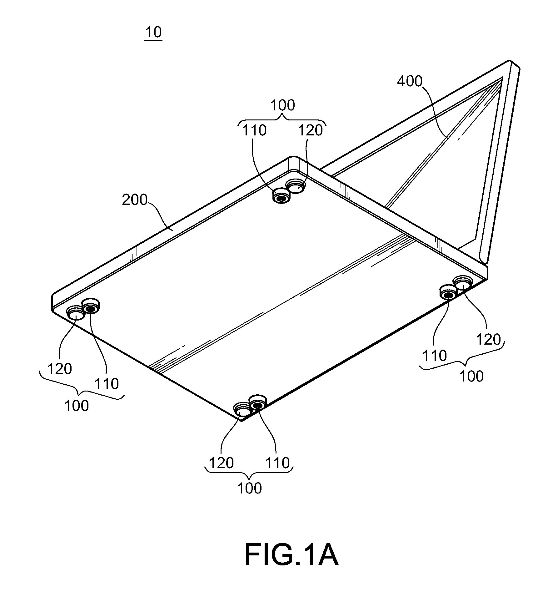
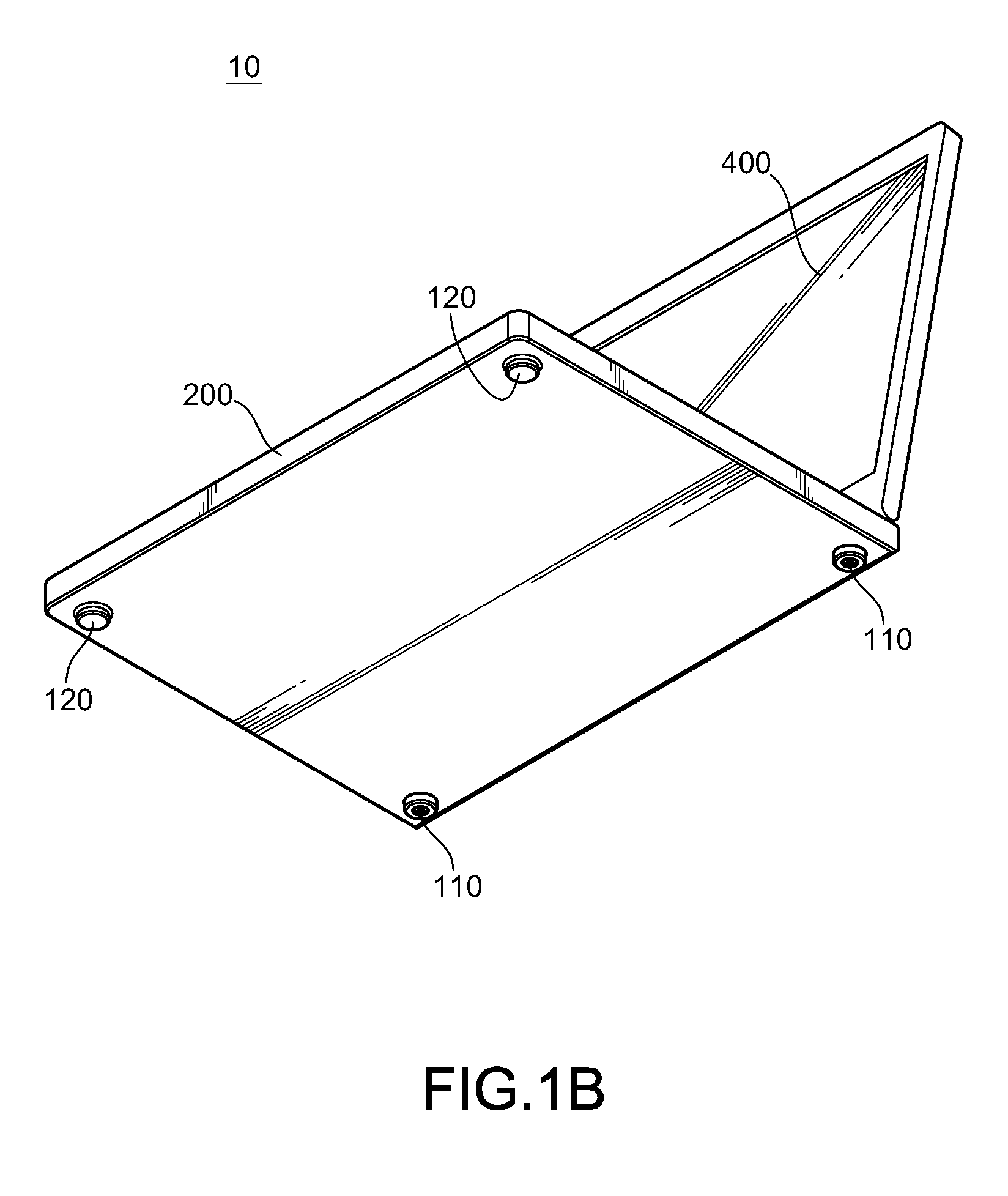
[0022]Referring to FIGS. 1A-1C, schematic three-dimensional views of embodiments according to the present invention are shown. A pad structure 100 according to the present invention is disposed on the bottom of a casing 200 of an electronic device 10, and has a skidproof piece 110 and a slide piece 120. The slide piece 120 can be adjacent to the skidproof piece 110, and closer to the edge of the casing 200 relative to the skidproof piece 110 (as shown in FIG. 1A), or on the bottom of the casing 200 at the other side opposite to the skidproof piece 110 (as shown in FIG. 1B and 1C). Moreover, the slide piece 120 is made of a material having a low static friction force, such as aluminum magnesium alloy and glass-reinforced plast...


PUM


Abstract

A pad structure is disposed on the bottom of a casing of an electronic device, which includes a skidproof piece and a slide piece. The skidproof piece is used for securing and supporting the electronic device on a plane. When the electronic device is at an oblique angle opposite to the plane, and drags the skidproof piece away from the plane, the slide piece contacts with the plane, and the electronic device is enabled to move on the plane by the slide piece.

Description

CROSS-REFERENCE TO RELATED APPLICATIONS[0001]This non-provisional application claims priority under 35 U.S.C. §119(a) on Patent Application No(s). 097135708 filed in Taiwan, R.O.C. on Sep. 17, 2008 the entire contents of which are hereby incorporated by reference.BACKGROUND OF THE INVENTION[0002]1. Field of Invention[0003]The present invention relates to a pad structure, and more particularly a pad structure disposed on the bottom of a casing of an electronic device.[0004]2. Related Art[0005]For a housing of a common electronic device such as a computer, a host, and a screen, pads are generally disposed at periphery of the casing bottom, which can assist in the firm arrangement of the electronic device on a plane such as a desktop and a floor. The pads also support the electronic device to a certain height, thus avoiding the casing of the electronic device from directly contacting with the desktop or the floor to influence the performance of the electronic device due to the heat gen...

Claims


Application Information

Patent Timeline
IPC IPC(8): A47B97/00
CPCH05K5/0234
Inventor SU, HENG-YUNG
Owner MICRO-STAR INTERNATIONAL
Why Eureka
Try Eureka