Cross-flow fan made of resin and method of manufacturing the same

a cross-flow fan and resin technology, applied in the direction of wind motor components, non-positive displacement fluid engines, liquid fuel engine components, etc., can solve the problems of high manufacturing cost, inability to meet the requirements of air blowing performance, and structure suitable for improving air blowing performance, so as to reduce the number of portions

Inactive Publication Date: 2010-06-24
DAIKIN IND LTD
View PDF9 Cites 16 Cited by
  • Summary
  • Abstract
  • Description
  • Claims
  • Application Information

AI Technical Summary

Benefits of technology

[0024]With this manufacturing method of a resin cross flow fan, since the projecting portions are formed so as to extend along one side of the blade...

Problems solved by technology

This causes a problem of higher manufacturing cost.
This causes a problem of an increased number of circular disks 211a. This also causes a problem that a structure suitable for improving air blowing performance, such as where the blades 211b are disposed inclined with respect to the rotation axis or the like, cannot be made.
When i...

Method used


Image

  • Cross-flow fan made of resin and method of manufacturing the same
  • Cross-flow fan made of resin and method of manufacturing the same
  • Cross-flow fan made of resin and method of manufacturing the same

Examples


first embodiment

(1) Structure of a Resin Cross Flow Fan

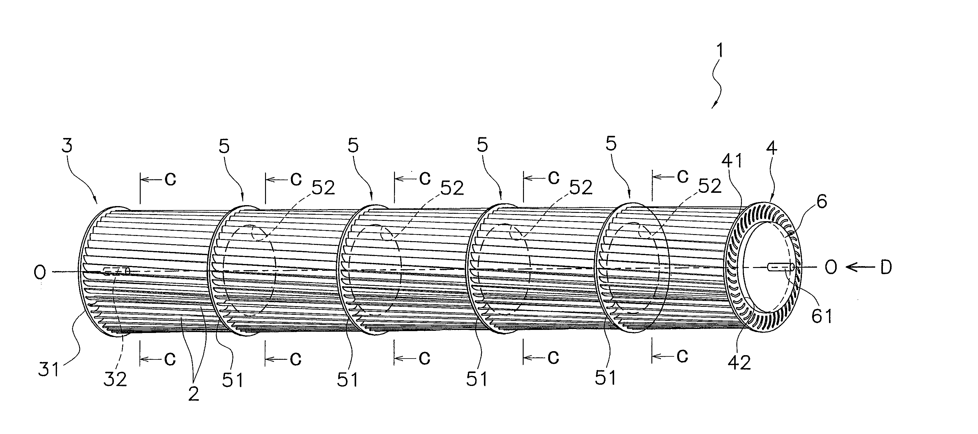
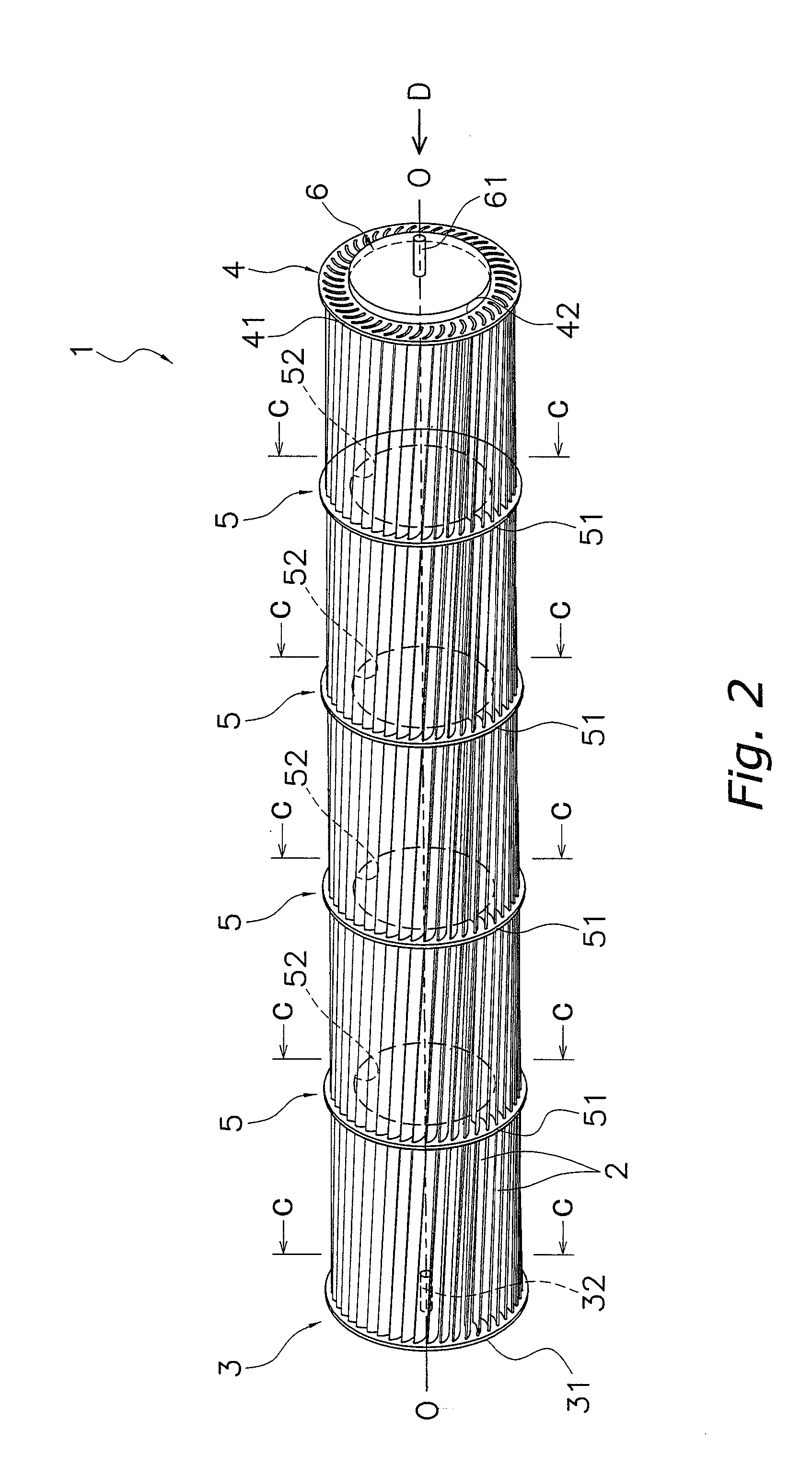
[0059]FIG. 2 shows an external perspective view of a resin cross flow fan 1 according to a first embodiment of the present invention. Note that line O-O is a rotation axis line of the resin cross flow fan 1 (hereinafter line O-O is referred to as “rotation axis”).

[0060]The resin cross flow fan 1 mainly includes a plurality of blades 2, a first end plate 3, a second end plate 4, and support plates 5.

[0061]The plurality of blades 2 are long resin members annually disposed about the rotation axis and extending the entire length of the resin cross flow fan 1. Each blade 2 has a cross section having a generally circular arc shape. In addition, each blade 2 is disposed inclined at predetermined angle instead of in parallel to the rotation axis, in order to improve air blowing performance including noise reduction and the like. In addition, an ABS resin and the like may be used as the material constituting the blades 2.

[0062]The first end plate 3 is a...

second embodiment

(1) Structure of Resin Cross Flow Fan

[0089]FIG. 14 shows an external perspective view of a resin cross flow fan 101 according to a second embodiment of the present invention. As is the case with the resin cross flow fan 1 in the first embodiment, the resin cross flow fan 101 according to the second embodiment of the present invention is a fan that uses the plurality of long blades 2 that extend the entire length of the resin cross flow fan 101 and mainly includes the plurality of blades 2, a first end plate 103, a second end plate 104, and support plates 105. Note that the resin cross flow fan 101 has a structure similar to that of the resin cross flow fan 1 except for that the plates 103, 104, and 105 are different from the plates 3, 4, and 5 of the resin cross flow fan 1 in the first embodiment. Therefore, descriptions are given below with respect to the structures of the plates 103, 104, and 105.

[0090]As shown in FIGS. 15 and 16, as is the case with the first end plate 3 of the r...

example 1

(4) Modified Example 1

[0108]With the above described resin cross flow fan 101, as shown in FIGS. 16, 18, and 20, the portions 35a, 45a, and 55a of the pressing portions 35, 45, and 55, which come into contact with the concave side of the blades 2, have a slightly pointed shape, and the contact therebetween is substantially a line contact. However, they may be configured to extend along the concave side of the blades 2 such that the contact therebetween is a planer contact. More specifically, the support plates 105 are described by way of example (descriptions of the plates 103 and 104 are omitted). As shown in FIG. 22, the portions 55a of the pressing portions 55 are configured in a flat shape that extends along the concave side of the blades 2. This enables a further improvement of the close contact condition between the blades 2 and the projecting portions 34, 44, and 54 by the pressing portions 35, 45, and 55.


PUM

PropertyMeasurementUnit
Thicknessaaaaaaaaaa
Transmittivityaaaaaaaaaa

Abstract

A resin cross flow fan and a method for manufacturing a resin cross flow fan are provided in which an annealing step can be omitted and the number of circular disks can be reduced, and which provides improved fan strength and air blowing performance. A resin cross flow fan is disposed with a plurality of blades and a plurality of plates. The plurality of blades are annually disposed about a rotation axis. Insertion portions each constituted by a hole or a groove into which each blade is inserted and projecting portions that projects from the periphery of the insertion portions in a direction of the rotation axis are formed on each of the plurality of plates disposed spaced apart in the direction of the rotation axis. Each blade is fixed to the projecting portions by laser welding.

Description

TECHNICAL FIELD[0001]The present invention relates to a resin cross flow fan and a manufacturing method thereof.BACKGROUND ART[0002]As a conventional resin cross flow fan, a fan manufactured by so-called ultrasonic welding is well known in which, as shown in FIG. 1, a resin molded body 211 integrally formed by a circular disk 211a and numerous blades 211b by a mold is provided (resin molding step), subsequently these resin molded bodies 211 are superposed in a direction of a rotation axis of the fan, and then an assembly of these resin molded bodies 211 is subjected to ultrasonic vibration while being pressurized in the direction of the rotation axis: thereby these resin molded bodies 211 are molded to each other (ultrasonic welding step). Here, members disposed at both ends of the assembly of the resin molded bodies 211 shown in FIG. 1 (in FIG. 1, nine resin molded bodies 211 are superposed) in the direction of the rotation axis are resonant bodies called cones 221 and 222 for tran...

Claims


Application Information

Patent Timeline
IPC IPC(8): F04D29/26B23K26/00F04D17/04
CPCF04D17/04F04D29/023F04D29/283B29C65/1635Y10T29/49329B29C66/5346B29C66/543B29L2031/08B29C66/5344F05D2230/234F05D2300/44F04D29/38
Inventor NISHINO, HISANORI
Owner DAIKIN IND LTD
Why Eureka
Try Eureka