

Breathing apparatus structure with two-stage reduced-pressure spare air bottle head
- Summary
- Abstract
- Description
- Claims
- Application Information
AI Technical Summary
Benefits of technology
Problems solved by technology
Method used
Image

Examples
Embodiment Construction
[0031]In order to make the structures, apparatuses, and features of the present invention more comprehensible, the preferred embodiments of the present invention are described in detail below with reference to the accompanying drawings.
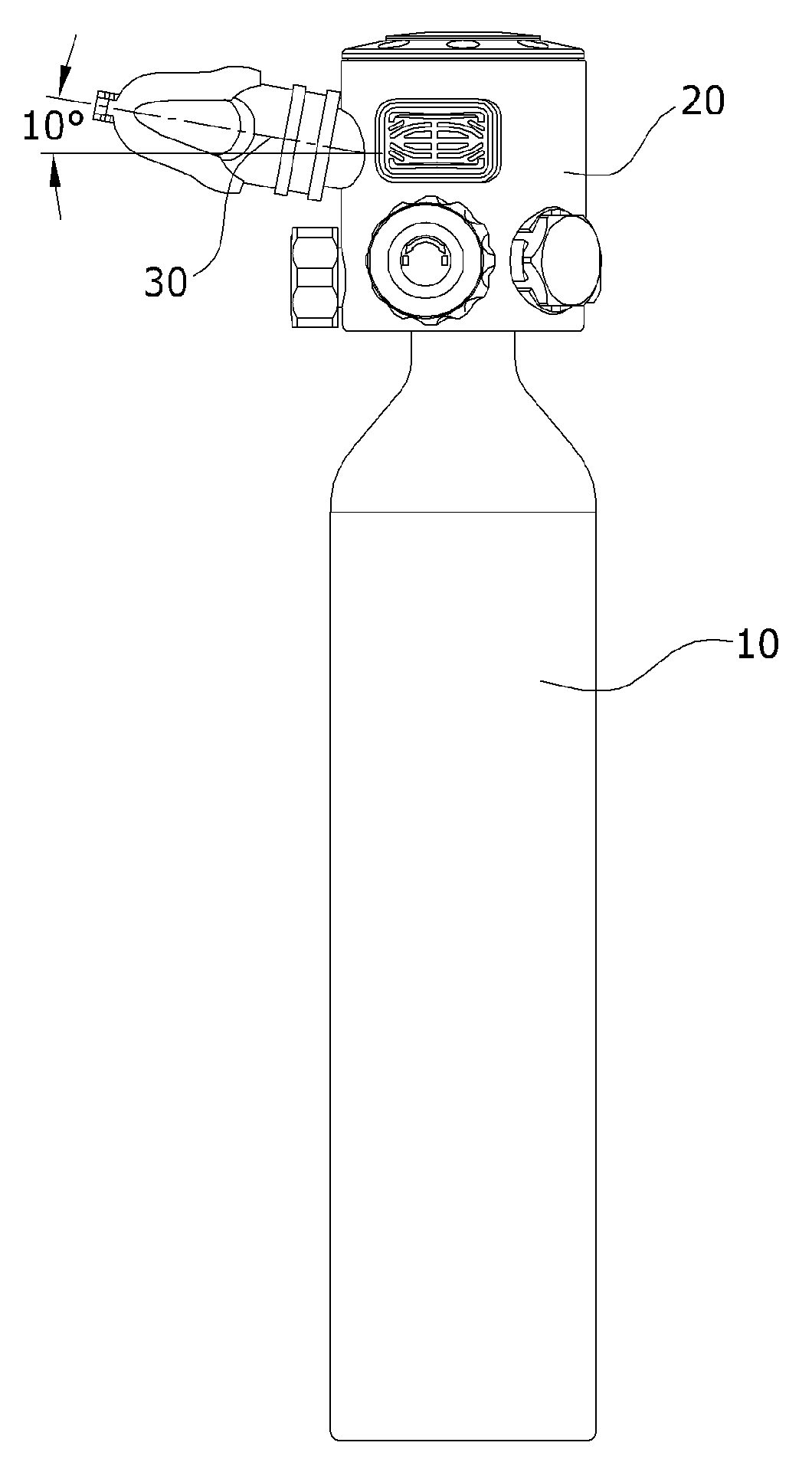
[0032]Referring to FIGS. 4-7, a breathing apparatus structure with a two-stage reduced-pressure spare air bottle head according to an embodiment includes: an air bottle head 20 mounted at an outlet end of a spare air bottle 10 and used for adjusting an air pressure, and an inhalation mouthpiece 30 disposed in a manner of extending outwards from a low-pressure valve 26 of the air bottle head 20, so as to provide an air at a suitable pressure to a diver or drowning person for emergency use. The air bottle head 20 is mainly provided with a connector 21, an air-filling head 22, a safety bolt 23, an air bottle head switch 24, a high pressure reducing valve 25, and a low-pressure valve 26 thereon. The air bottle head switch 24, the high pressure reducing va...
PUM
 Abstract
Description
Claims
Application Information