Sealing device

a sealing device and electrode technology, applied in the direction of furnace components, electric discharge heating, lighting and heating apparatus, etc., can solve the problems of weakened sealing, inability to allow air into the furnace, wear of sealing that is in contact with the external surface of the electrode, etc., to achieve excellent sealing, not worn, not weakened

Inactive Publication Date: 2014-09-16
OUTOTEC OYJ
View PDF46 Cites 1 Cited by
  • Summary
  • Abstract
  • Description
  • Claims
  • Application Information

AI Technical Summary

Benefits of technology

[0015]An advantage of the invention is that as the gas flow is discharged from the slit nozzle encasing the electrode in a direction that is, with respect to the horizontal plane, oriented at an angle that is inclined slightly upwards, and that is, with respect to the furnace interior, pointed outwardly, gas leakages out of the furnace can be prevented when positive pressure prevails inside the furnace and, on the other hand, air leakages into the furnace can be prevented when negative pressure prevails inside the furnace, and the gap between the electrode and the sealing device is practically closed by the effect of stagnation pressure. The arrangement according to the invention functions at all times, irrespective of whether a negative or positive pressure prevails in the furnace. The pressure in the furnace may vary for example from a negative pressure of −70 Pa to a positive pressure of 22 Pa, with respect to the ambient air pressure. This means that excellent sealing can be provided by the sealing device in all operating conditions of the furnace.
[0016]A further advantage of the invention is that the sealing device is not worn, and the sealing is not weakened, even if the electrode was somewhat out-of-round and uneven. Thus the device has a long maintenance interval. The sealing device does not include any hydraulics using water, wherefore water leakages cannot occur in the furnace. Yet another advantage is that air leakages to the furnace and gas leakages from the furnace are efficiently prevented, in which case the wearing of the electrode is reduced.
[0017]In an embodiment of the sealing device, the gas flow is discharged through the slit nozzle at an angle that is about 15°-25° with respect to the horizontal plane.
[0018]In an embodiment of the sealing device, the distance of the slit nozzle from the outer surface of the electrode is about 10-40 mm.
[0019]In an embodiment of the sealing device, the nozzle slit height of the slit nozzle is about 5 mm.
[0020]In an embodiment of the sealing device, the gas flow rate from the slit nozzle is at least about 10 m / s.

Problems solved by technology

A drawback with mechanical sealing devices arises in that in practice, the electrode surface is not perfectly cylindrical and smooth, but it may be out-of-round and uneven, which results in the wearing of the sealings that are in contact with the external surface of the electrode as the electrode moves vertically.
Thus the sealing is weakened.
In arc furnaces with a reducing atmosphere, any leakage of air into the furnace cannot, however, be allowed.
Again, any leakage of carbon monoxide to the exterior of the furnace cannot be allowed, because carbon monoxide is very toxic.
Further, if air flows into the furnace, the carbon monoxide begins to burn and rises the temperature at the aperture very high, thus destroying the furnace structures.
Leakage air causes burning and rapid wearing of the graphite, which increases the consumption of both the Söderberg electrode paste and coke.
Another drawback is the use of water in connection with sealing, because in a damage situation water may accidentally get into the furnace.
When water is introduced into the furnace atmosphere with a high temperature, a dangerous water-gas explosion may occur.

Method used


Image

  • Sealing device
  • Sealing device
  • Sealing device

Examples


Embodiment Construction

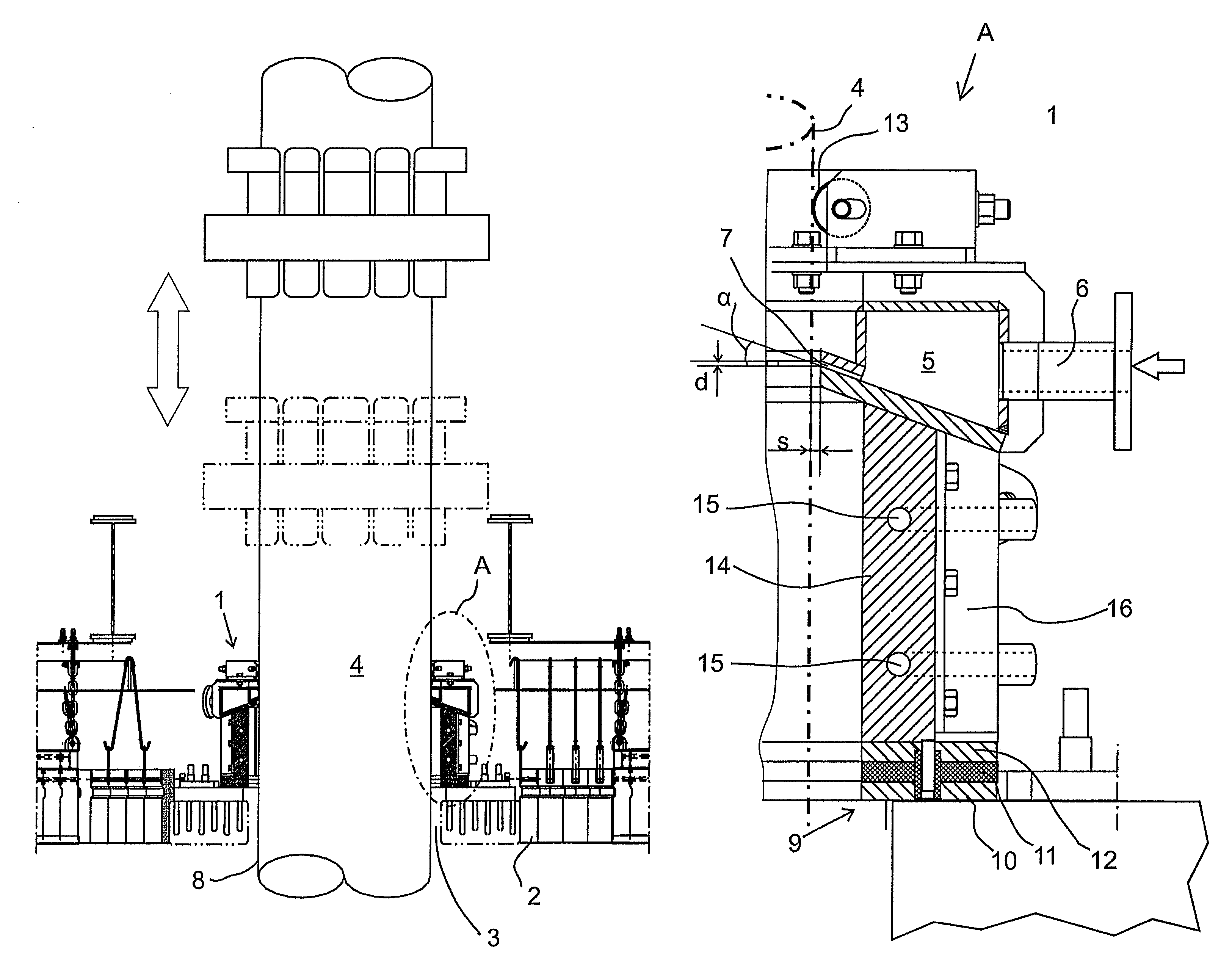
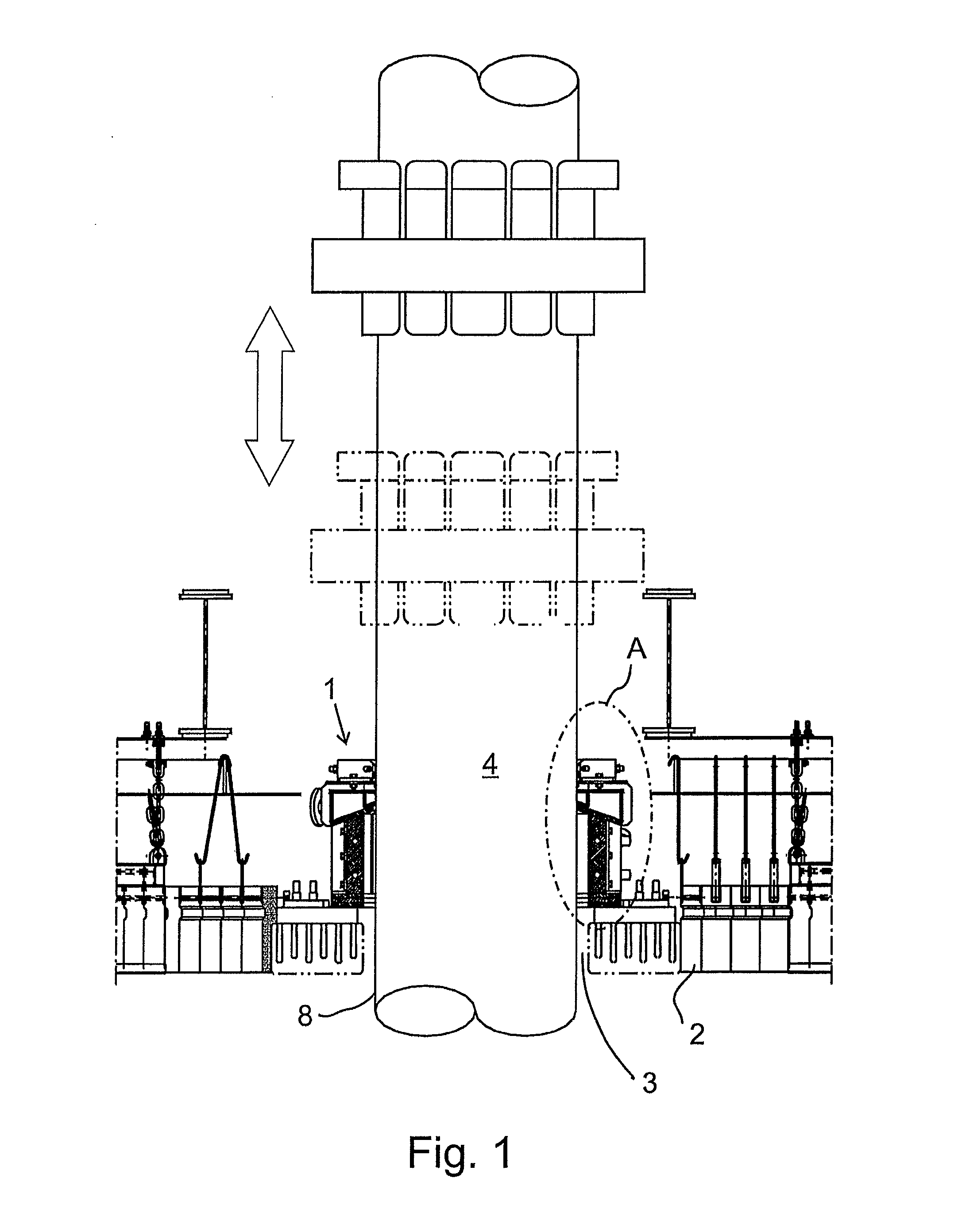
[0036]FIG. 1 shows part of the arc furnace ceiling 2, provided with an aperture 3 that constitutes the feed-through for the vertical rod electrode 4. On top of the edge of the aperture 3, there is arranged the sealing device 1 shown in FIG. 3, said sealing device encasing the electrode 4. The electrode 4 is a so-called Söderberg electrode, containing so-called Söderberg electrode paste inside a cylindrical steel casing 8. In another embodiment, the electrode can be a graphite electrode. The diameter of the electrode 4 can be of the order 500-1200 mm. The sealing device, prevents the leakage of gases from inside the furnace through the aperture 3 to the atmosphere, and on the other hand, it also prevents air leakages into the furnace.

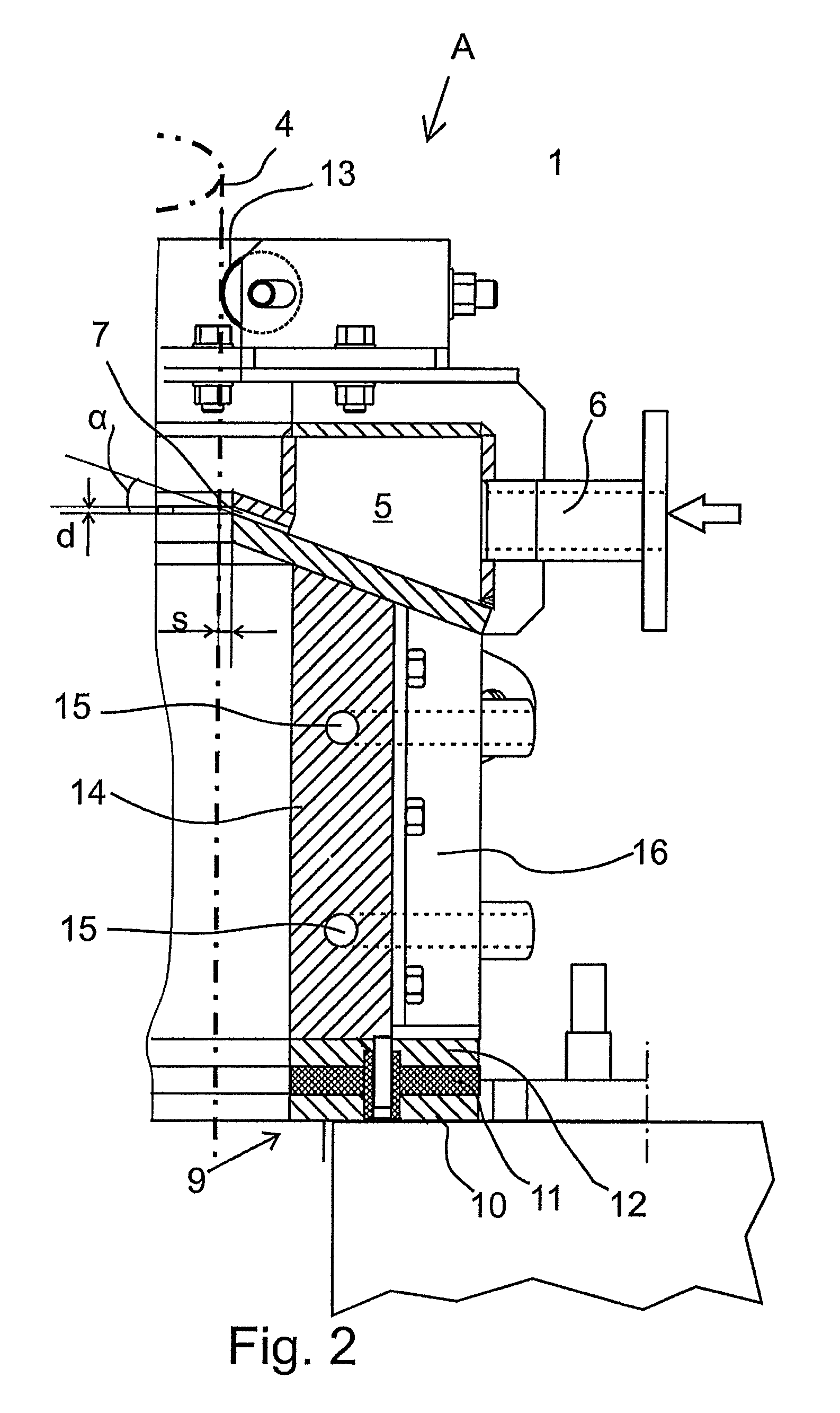
[0037]From FIGS. 2 and 3 it is apparent in more detail that the sealing device 1 includes a gas distribution chamber 5 provided with an inlet channel 6, through which air or nitrogen is fed in the gas distribution chamber 5. From the gas distribution cha...


PUM

PropertyMeasurementUnit
distanceaaaaaaaaaa
heightaaaaaaaaaa
gas pressureaaaaaaaaaa

Abstract

A sealing device is arranged around a rod electrode extending vertically through an aperture made in the ceiling of an arc furnace and being vertically movable inside the furnace to prevent the access of gases from the furnace through the aperture to the atmosphere, and on the other hand to prevent air from flowing from the atmosphere into the furnace. The sealing device comprises a gas distribution chamber provided with an inlet channel for feeding essentially passive gas, such as nitrogen or air, into the gas distribution chamber. The sealing device also includes a slit nozzle encasing the electrode, through which nozzle a gas jet is arranged to be discharged from the gas distribution chamber towards the electrode in a direction that is at an angle with respect to the horizontal plane and has a slightly upwards inclined orientation, and that is, with respect to the furnace interior, pointed outwardly, so that the sealing is carried out owing to the effect of the created stagnation pressure.

Description

FIELD OF THE INVENTION[0001]The invention relates to the sealing of electrodes in electric-arc furnaces used in metallurgy. The object of the invention is a sealing device defined in the preamble of claim 1.BACKGROUND OF THE INVENTION[0002]An arc furnace is an electrically operated furnace used for melting metal and / or for cleaning slag. The operation of the furnace is based on a light arc that burns either between separate electrodes, or between electrodes and the material to be melted. The furnace may be operated either by AC or DC current. Heat is created in the light arc, and also in the material to be melted, in case the light arc burns between the material and the electrodes. Power is conducted to vertical electrodes that are located symmetrically in a triangle with respect to the midpoint of the furnace. The assembly depth of the electrodes in the furnace is continuously adjusted, because they are worn at the tips owing to the light arc.[0003]The electrodes extend into the fu...

Claims


Application Information

Patent Timeline
Patent Type & Authority Patents(United States)
IPC IPC(8): H05B7/12E21B33/06F16J15/08F16J15/02H05B7/101H05B7/107H05B7/10H05B7/08H05B7/06F27B14/04H05B3/60C03B5/027
CPCH05B7/12F27D99/0073
Inventor XIA, JILIANGAHOKAINEN, TAPIOSAARINEN, RISTO
Owner OUTOTEC OYJ
Why Eureka
Try Eureka