Motor

a motor and motor body technology, applied in the field of motors, can solve the problems of difficult to reduce compromise manufacturing efficiency and accuracy, etc., and achieve the effect of minimizing the space required for the connection and minimizing the dimensions of the motor

Active Publication Date: 2010-08-12
NIPPON DENSAN CORP
View PDF14 Cites 43 Cited by
  • Summary
  • Abstract
  • Description
  • Claims
  • Application Information

AI Technical Summary

Benefits of technology

[0009]In view of the aforementioned problems, preferred embodiments of the present invention provide an efficient connection between the external power source and the bus wire while minimizing the space required for the connection and minimizing the dimensions of the motor.

Problems solved by technology

Therefore, according to a method in which a busbar is used to connect the bus wire from the armature to an external power source, it is difficult to reduce the dimensions of the motor while manufacturing efficiency and accuracy are compromised.

Method used


Image

  • Motor
  • Motor
  • Motor

Examples


Embodiment Construction

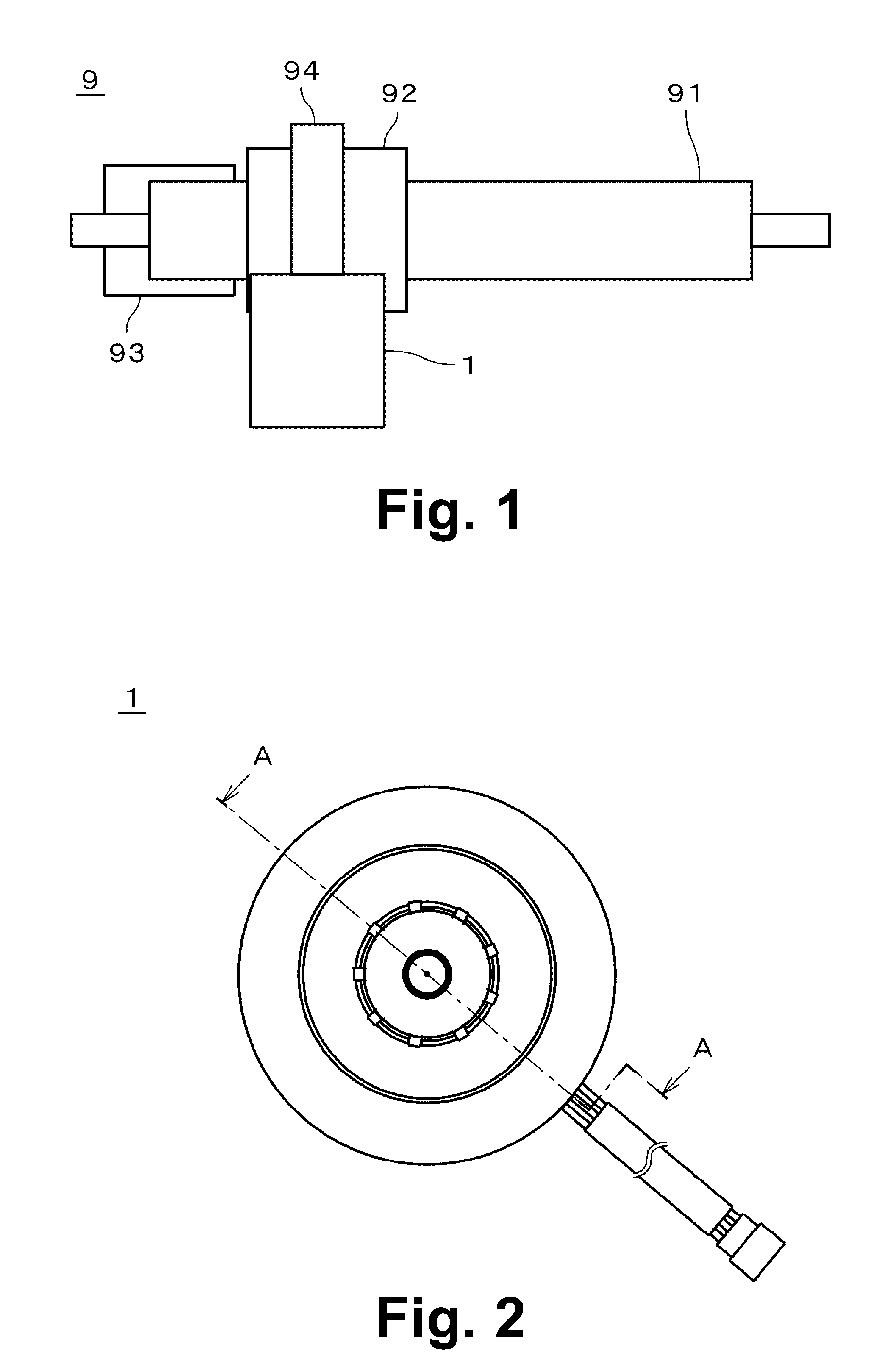
[0040]FIG. 1 is a schematic drawing showing a power steering device 9 including a motor according to a first preferred embodiment of the present invention. The power steering device 9 is typically used in a vehicle such as a passenger vehicle or the like to assist an operator of the vehicle in steering the vehicle, for example. The power steering device 9 preferably includes a shaft portion 91 which is connected to a steering wheel or a steering mechanism, a torque sensor 92 which detects a torque applied to the steering wheel, a control unit 93 (e.g., ECU or the like) which calculates a force necessary to assist the operator based on an output from the torque sensor 92, a motor 1 which generates a rotary force based on an output from the control unit 93, and a decelerating mechanism 94 which conducts the rotary force of the motor 1 to the steering mechanism.

[0041]In a motor vehicle having the power steering device 9, it becomes possible for the motor 1 of the power steering device ...


PUM


Abstract

A motor includes a plurality of bus wires of a common phase which are put together before being guided in a common passage to minimize the space arranged to guide the bus wires. Also, the bus wires of a common phase are easily insulated from those of different phases, and an axial height of the motor is reduced. Further, a radial width necessary to guide the bus wires is reduced, and an axial height of the motor including a sensor portion which detects a rotary position of the motor is reduced. Also, the bus wires are easily extended from the armature, and an amount of work required to connect the bus wires and the terminals is reduced. Furthermore, the connection terminal portion does not interfere with the bus wires when they are being guided.

Description

BACKGROUND OF THE INVENTION[0001]1. Field of the Invention[0002]The present invention relates to a motor, and more particularly to a technology used to connect a bus wire of an armature of a motor to an external power source.[0003]2. Description of the Related Art[0004]A motor typically includes an armature having a plurality of coils arranged in an annular shape via which a multiple phase alternating current is supplied. There are many methods used to prevent coils of different phases from making contact with one another inside the armature. For example, Japanese Laid-Open Patent Publication (S) 61-227648 discloses an armature which includes two groove portions having an annular shape arranged at an upper surface and a lower surface of an insulating layer which cover a yoke portion of an annular shape, wherein lead wires of each phase are accommodated in different groove portions so as to avoid the contact among the lead wires.[0005]In an armature disclosed in Japanese Laid-Open Pa...

Claims


Application Information

Patent Timeline
Patent Type & Authority Applications(United States)
IPC IPC(8): H02K11/00
CPCH02K11/0015H02K3/522H02K11/21
Inventor KATAOKA, NAKABAOTSUJI, MOTOFUMIYAMASHITA, YOSHIAKI
Owner NIPPON DENSAN CORP
Why Eureka
Try Eureka