Signalling or emergency light-emitting device

a technology of emergency light and signal, which is applied in the direction of identification means, lighting support devices, ways, etc., can solve the problems of lack of stability in the structure of the device as described and depicted, and achieve the effect of reducing loss resistance and increasing antenna efficiency

Inactive Publication Date: 2010-08-12
SOBEI SRL
View PDF6 Cites 13 Cited by
  • Summary
  • Abstract
  • Description
  • Claims
  • Application Information

AI Technical Summary

Benefits of technology

[0007]Advantageously, the seal serves to protect an antenna of the radio frequency transceiver and reduces its loss resistance, increasing the antenna efficiency.

Problems solved by technology

However, the structure of the device as described and depicted appears lacking of stability in its rest just for its puck shape.

Method used


Image

  • Signalling or emergency light-emitting device
  • Signalling or emergency light-emitting device
  • Signalling or emergency light-emitting device

Examples


Embodiment Construction

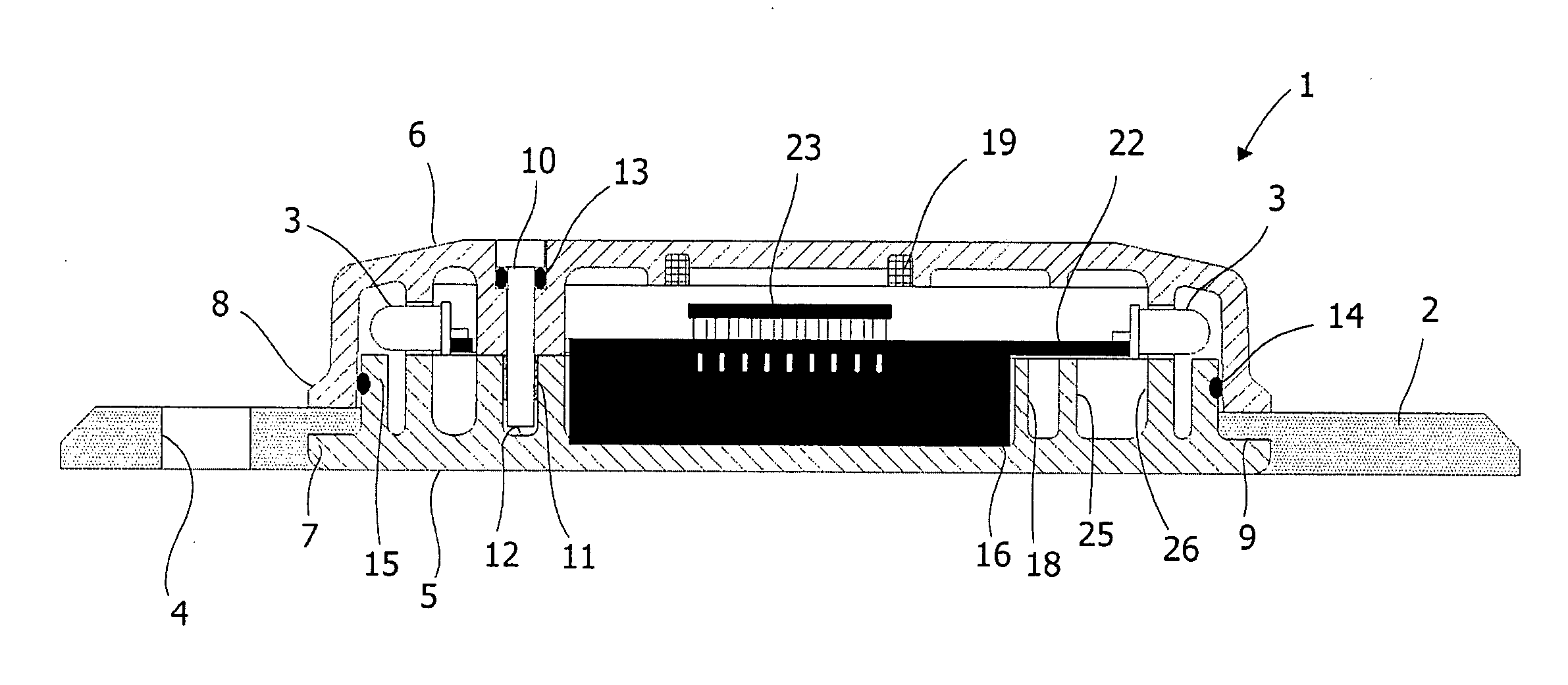
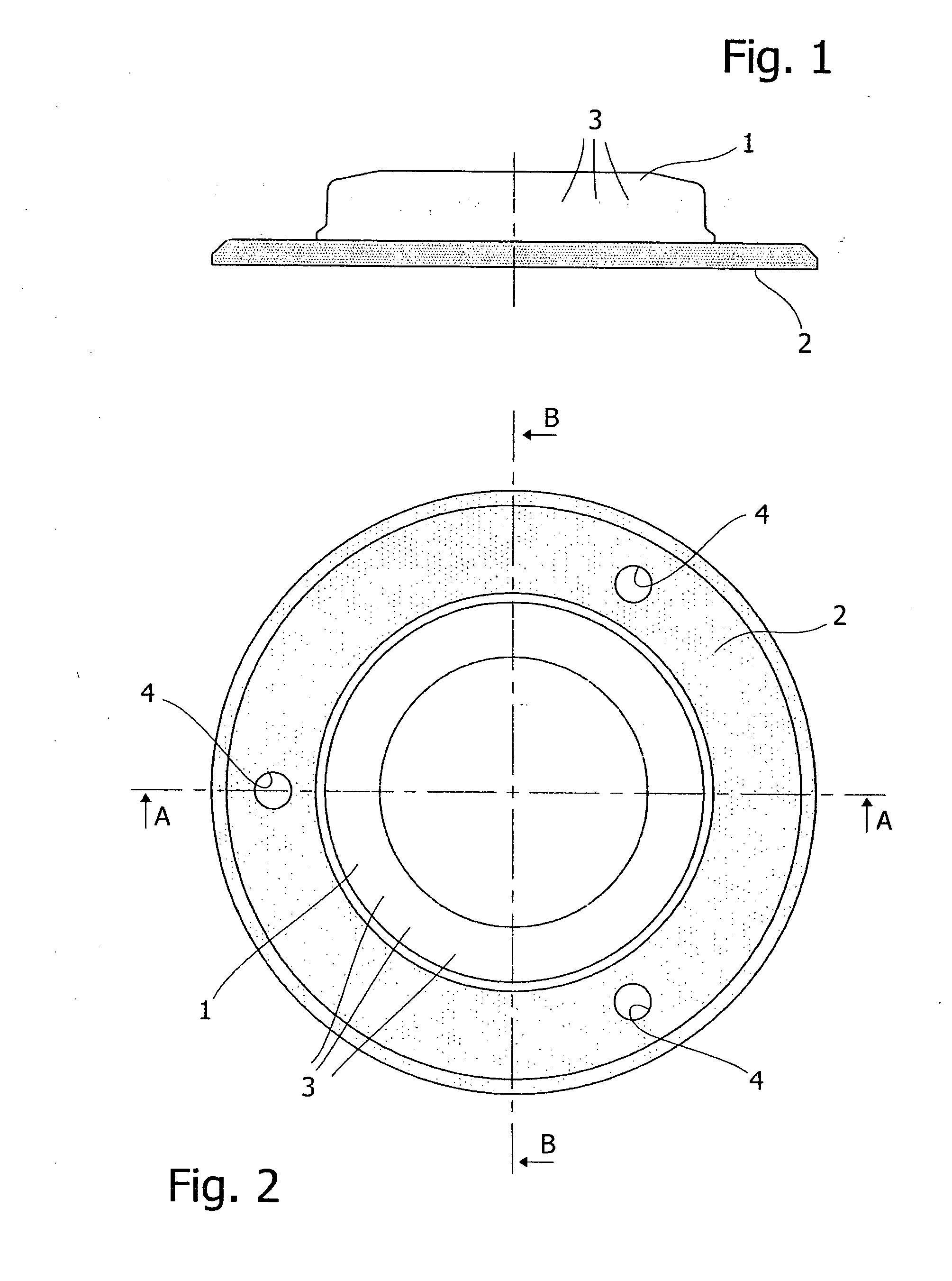
[0015]Referring to the drawings, in FIGS. 1 and 2 there is diagrammatically shown a general aspect of the device, comprising a shell 1 and a seal 2 that is around the shell 1 and extends a rest surface thereof. Inside the shell 1 there is a multiplicity of light-emitting diodes or LEDs generally indicated as 3. LEDs 3 provide a laterally directed cone of light, which is emitted according to various known ways and thus not further described. The seal 2 is made generally of rubber, preferably of nitrile rubber. Holes 4 are provided in the seal 2 to receive and retain magnets (not shown) in order to improve the adhesion of the illumination device to metal surfaces such as car bodies.

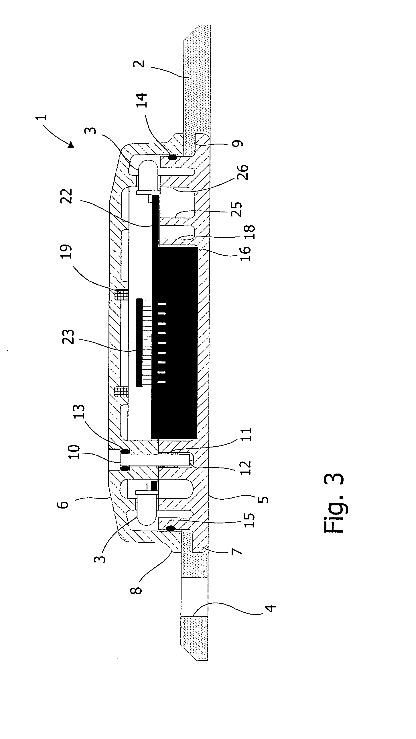
[0016]More in detail, with reference to FIG. 3, that shows a diagrammatic transversal cross-section according to line A-A of the illumination device in FIG. 2, the shell 1 is comprising of a base 5 and a cover 6. The base 5 and the cover 6 are depicted and described more in detail below with reference to FI...


PUM


Abstract

A signalling or emergency light-emitting device comprises a shell (1) that is made of a watertight transparent material and is provided with a crush resistant structure, containing a LED illumination circuit which is provided with a battery (16) rechargeable through a coil (19) that can be linked in its magnetic flux with an inductive power source, with a microprocessor (22) and a radiofrequency transceiver (23). The shell (1) comprises a base (5) and a cover (6) that are joined together by means of a series of fixing screws (10), a seal (2) that extends radially and enlarges the rest surface for the base (5) is interposed peripherally between the base (5) and the cover (6).

Description

TECHNICAL FIELD[0001]The present invention relates to a signalling or emergency light-emitting device.BACKGROUND OF ART[0002]U.S. Pat. No. 7,088,222 describes a device of this kind, comprising a puck-shaped shell of transparent material containing a LED (light emission diode) illumination circuit, which is provided with a battery rechargeable, among other, by means of an inductive power source, the circuit further comprising a microprocessor to control the operation thereof and a radiofrequency transceiver for the connection to other similar illumination apparatuses or other devices. In the device cited the shell of transparent material, which is waterproof and provided with a crush resistant structure, is surrounded by an external layer of opaque plastics having windows through which the light emitted by LED passes. Alternatively, the external layer, by which the shell, when it is made of two parts joined together, is sealed, can be also transparent, whereby windows are not require...

Claims


Application Information

Patent Timeline
Patent Type & Authority Applications(United States)
IPC IPC(8): F21L4/00
CPCB60Q1/2615B60Q1/52B60Q7/00F21V21/0965G08B5/002F21V31/00F21W2111/00F21W2111/02F21V23/02
Inventor VITTOZZI, ANGELO
Owner SOBEI SRL
Why Eureka
Try Eureka