Dual-cross coil array-type magnetic resonant coupling wireless electric energy transmission coil structure

A technology of wireless power transmission and magnetic resonance coupling, which is applied in electrical component structure associations, transformer/inductor coils/windings/connections, circuits, etc., can solve problems such as limiting the convenience of equipment, occupying active space, and hidden dangers in safe use of electricity , to achieve the effect of improving transmission efficiency and transmission distance, improving coupling strength, and increasing coupling strength

Pending Publication Date: 2019-05-10
CHENGDU SPROUTING TECH CO LTD
View PDF0 Cites 0 Cited by
  • Summary
  • Abstract
  • Description
  • Claims
  • Application Information

AI Technical Summary

Problems solved by technology

[0002] With the continuous development of electronic information technology and automation control technology, various home appliances, consumer electronics, mobile communication equipment, etc. have been widely popularized. However, traditional household appliances rely Electronic devices with built-in batteries also need a wired connection between the charging cable and the power outlet for charging, so we can see wires that provide power supply for these electronic devices everywhere
These wires not only occupy our activity space, limit the convenience of equipment use, but also create hidden dangers for safe use of electricity.

Method used


Image

  • Dual-cross coil array-type magnetic resonant coupling wireless electric energy transmission coil structure
  • Dual-cross coil array-type magnetic resonant coupling wireless electric energy transmission coil structure
  • Dual-cross coil array-type magnetic resonant coupling wireless electric energy transmission coil structure

Examples


Embodiment Construction

[0063] Exemplary embodiments of the present invention will now be described in detail with reference to the accompanying drawings. It should be understood that the implementations shown and described in the drawings are only exemplary, intended to explain the principle and spirit of the present invention, rather than limit the scope of the present invention.

[0064] An embodiment of the present invention provides a double cross coil array magnetic resonance coupled wireless power transmission coil structure, including a transmitting module for wireless power transmission and a receiving module for wireless power reception.

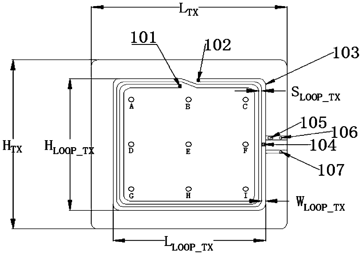
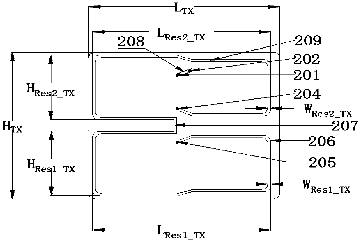
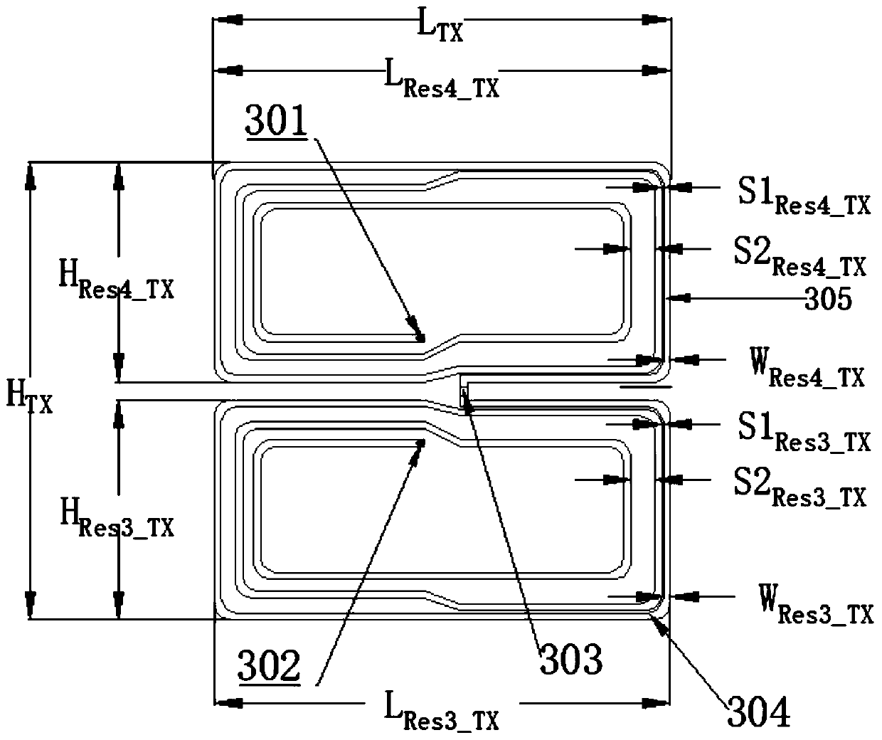
[0065] Wherein, the transmitting module is a three-layer flat structure, which includes a top-layer printed circuit structure, a middle-layer printed circuit structure, and a bottom-layer printed circuit structure printed on a dielectric substrate; the top-layer printed circuit structure includes an excitation coil 103, and the middle-layer printed circuit...


PUM

PropertyMeasurementUnit
Widthaaaaaaaaaa
Lengthaaaaaaaaaa
Widthaaaaaaaaaa

Abstract

The invention discloses a dual-cross coil array-type magnetic resonant coupling wireless electric energy transmission coil structure. The dual-cross coil array-type magnetic resonant coupling wirelesselectric energy transmission coil structure comprises an emission module and a receiving module, wherein the emission module is used for emitting wireless electric energy, the receiving module is used for receiving the wireless electric energy, the emission module is designed by horizontally arranging two cross coils in an array way, the coils are not overlapped, so that the transmission efficiency of a receiving coil at different transverse and longitudinal positions in an emission coil region is equalized, and the wireless charging and power supply requirement of a plurality of electronic equipment can be met. On the basis of magnetic resonant coupling wireless energy transmission scheme, the coil structure of a transceiving module is processed by a planar printed circuit, the miniaturization and the integration of a system are achieved, the production, installation and maintenance cost of the system is greatly reduced, and a stable and high-efficiency wireless charging or wirelesselectric energy supply scheme is provided for a portable computer, a communication product, a consumer electronic product and LED lighting equipment.

Description

technical field [0001] The invention belongs to the technical field of wireless power transmission, and in particular relates to the design of a double cross coil array type magnetic resonance coupling wireless power transmission coil structure. Background technique [0002] With the continuous development of electronic information technology and automation control technology, various home appliances, consumer electronics, mobile communication equipment, etc. have been widely popularized. However, traditional household appliances rely Electronic devices with built-in batteries also need a wired connection between the charging cable and the power outlet for charging, so we can see wires that provide power supply for these electronic devices everywhere. These wires not only occupy our activity space, limit the convenience of equipment use, but also create hidden dangers for safe use of electricity. Therefore, with the growing demand for portable devices and green energy syste...

Claims


Application Information

Patent Timeline
IPC IPC(8): H01F27/28H01F27/40H01F38/14
Inventor 喻易强李伟胡鹏飞
Owner CHENGDU SPROUTING TECH CO LTD
Why Eureka
Try Eureka