Multi-transmit and multi-receive magnetic resonance wireless charging system for medium power electronic equipment

A technology of electronic equipment and wireless charging, which is applied in the direction of output power conversion devices, transmission systems, near-field transmission systems, etc., can solve the problems of large volume, poor stability, and large power consumption at the receiving end, and achieve increased horizontal degrees of freedom, The effect of reducing power load pressure and reducing loss resistance

Active Publication Date: 2020-08-18
CHENGDU SPROUTING TECH CO LTD
View PDF7 Cites 0 Cited by
  • Summary
  • Abstract
  • Description
  • Claims
  • Application Information

AI Technical Summary

Problems solved by technology

[0008] The purpose of the present invention is to solve the technical problems of large receiving end, large power consumption, low efficiency, poor stability, serious heat generation and other technical problems in the existing magnetic resonance wireless charging design scheme that can be used for wireless charging of medium-power small electronic equipment, and meet the needs of small household appliances. And the built-in requirements of consumer electronics products for wireless charging solutions and the humanized requirements for the use of electronic products in the market, a multi-transmission and multi-reception magnetic resonance wireless charging system for medium-power electronic equipment is proposed

Method used


Image

  • Multi-transmit and multi-receive magnetic resonance wireless charging system for medium power electronic equipment
  • Multi-transmit and multi-receive magnetic resonance wireless charging system for medium power electronic equipment
  • Multi-transmit and multi-receive magnetic resonance wireless charging system for medium power electronic equipment

Examples


Embodiment Construction

[0043] Exemplary embodiments of the present invention will now be described in detail with reference to the accompanying drawings. It should be understood that the implementations shown and described in the drawings are only exemplary, intended to explain the principle and spirit of the present invention, rather than limit the scope of the present invention.

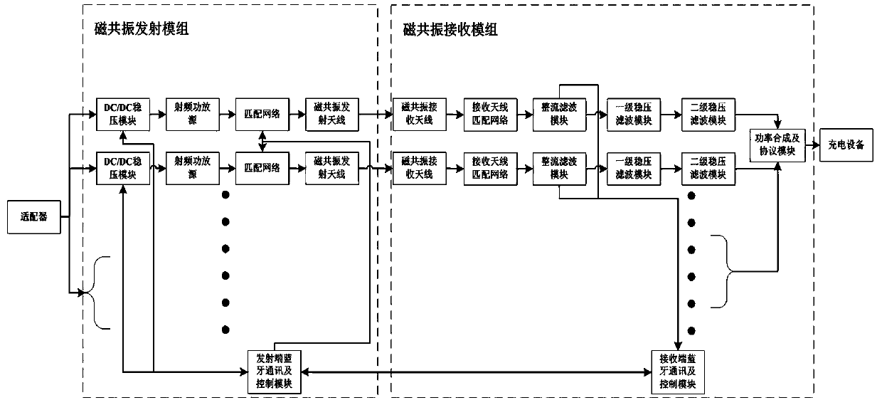
[0044] An embodiment of the present invention provides a multi-transmission and multi-reception magnetic resonance wireless charging system for medium-power electronic equipment, such as figure 1 As shown, it includes a magnetic resonance transmitting module and a magnetic resonance receiving module.

[0045] The magnetic resonance transmission module includes a Bluetooth communication and control module at the transmitting end and at least two magnetic resonance transmission channels. Each magnetic resonance transmission channel has the same structure and includes a sequentially connected DC / DC voltage regulator module,...


PUM


Abstract

The invention discloses a multi-transmit and multi-receive magnetic resonance wireless charging system for medium-power electronic equipment. The array structure composed of multiple transmitting antennas and the array structure composed of multiple receiving antennas in the wireless energy transmission system are coupled by magnetic resonance. The magnetic resonance coupling between them transmits the electromagnetic energy wirelessly from the transmitting end to the receiving end, and then performs power synthesis to realize the charging of medium-power electronic devices. The magnetic field multi-channel transmission and multi-channel reception scheme adopted in the present invention can ensure that in the case of high output power, the load power of each channel is equally divided, and the power carrying pressure of a single channel can be reduced, so that the design scheme and devices can be thinned and thinned to meet the needs of small and medium-sized The built-in requirements of wireless charging solutions for small power home appliances and consumer electronics products. The magnetic field multi-transmission and multi-reception scheme adopted in the present invention effectively improves the magnetic field coupling balance between the transmitting and receiving ends, increases the horizontal degree of freedom, and enables the receiving end to move freely in the transmitting area.

Description

technical field [0001] The invention belongs to the technical field of wireless energy transmission, and in particular relates to the design of a multi-transmission and multi-reception magnetic resonance wireless charging system for medium-power electronic equipment. Background technique [0002] With the continuous development of electronic information technology and automation control technology, various home appliances, consumer electronics, mobile communication equipment, etc. have been widely popularized. However, traditional household appliances rely Electronic devices with built-in batteries also need a wired connection between the charging cable and the power outlet for charging, so we can see wires that provide power supply for these electronic devices everywhere. These wires not only occupy our activity space, limit the convenience of equipment use, but also create hidden dangers for safe use of electricity. Therefore, with the growing demand for portable devices ...

Claims


Application Information

Patent Timeline
Patent Type & Authority Patents(China)
IPC IPC(8): H02J7/02H02J50/20H02J50/40H02J50/70
CPCH02J50/20H02J50/40H02J50/70H04B5/0037H04B5/0081H03F3/245H03F2200/451H03F1/52H02J50/12H02J50/402H02J50/80H01P3/081H02J7/02H02M3/155H04B2201/71346
Inventor 喻易强李伟
Owner CHENGDU SPROUTING TECH CO LTD
Why Eureka
Try Eureka