Coupling arrangement for a telescopic device

Inactive Publication Date: 2010-08-19
COLOPLAST AS
View PDF4 Cites 49 Cited by
  • Summary
  • Abstract
  • Description
  • Claims
  • Application Information

AI Technical Summary

Benefits of technology

[0023]In order to further secure that the extension member is not pushed back into the first tubular element after it has been us

Problems solved by technology

However, this product mai

Method used


Image

  • Coupling arrangement for a telescopic device
  • Coupling arrangement for a telescopic device

Examples


Embodiment Construction

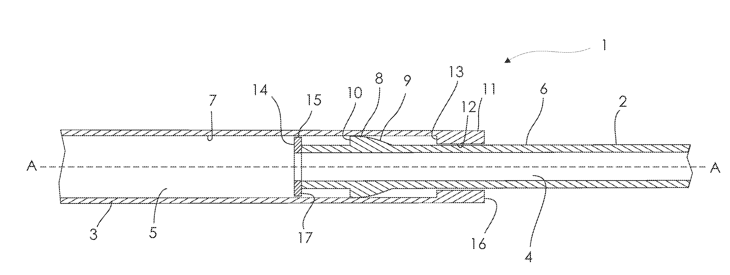
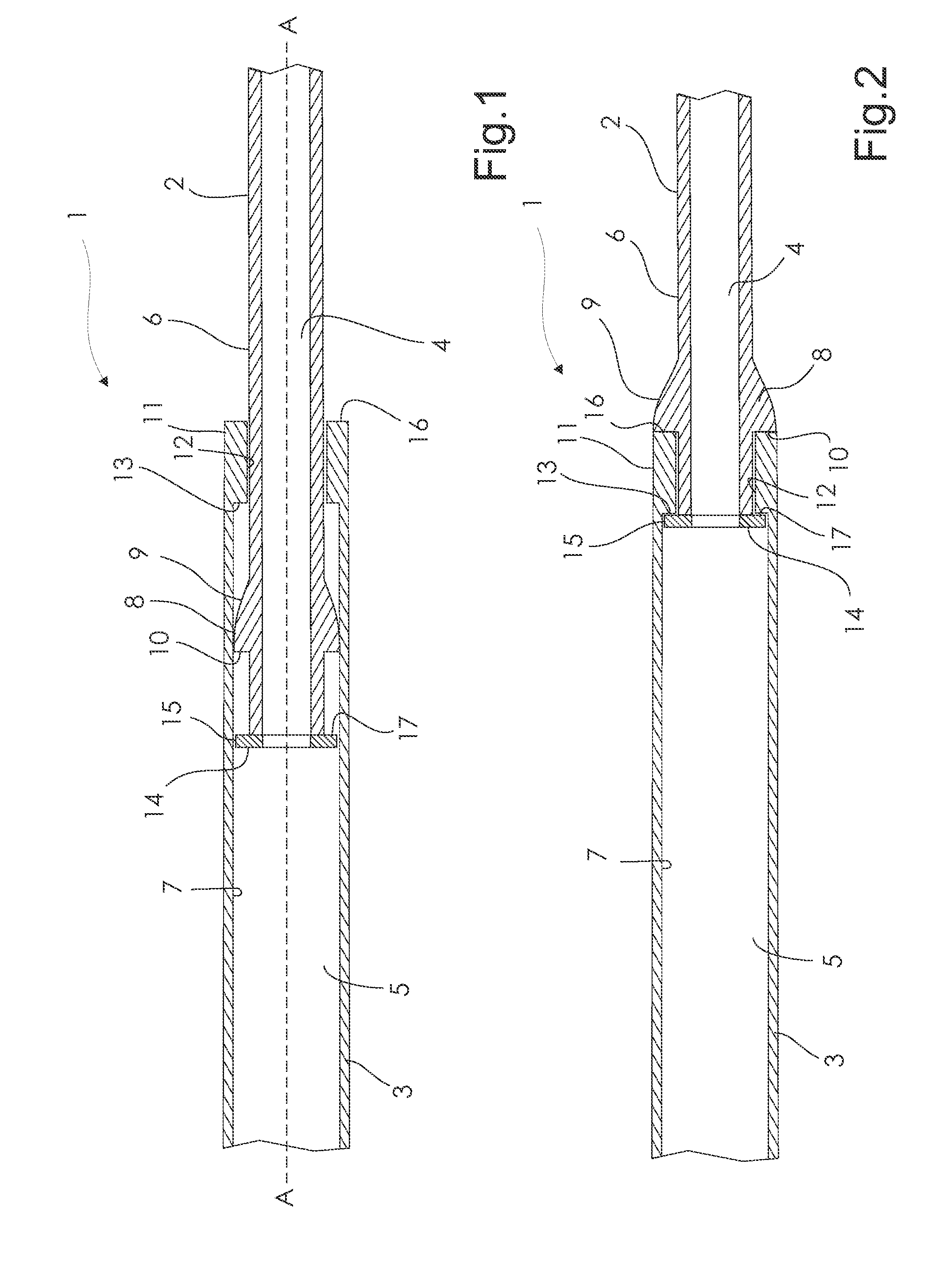
[0030]A telescopic intermittent catheter 1 is shown partly and in section in FIG. 1 around a first axis A-A. The catheter is formed of a proximal section 2 (corresponding to the extension member described above) and a distal section 3 (corresponding to the first tubular element described above).

[0031]Both sections are formed as tubular elements, wherein the distal section 3 defines a first passageway 5 and the proximal section 2 defines a second passageway 4 through which urine may flow in a flow direction from the first proximal section to the distal section during use.

[0032]The outer surface 6 of the proximal section 2 has a circumference, which is smaller than the circumference of the inner surface 7 of the distal section 3, so that the proximal section 2 at least partly can be displaceable placed within the first passageway 5.

[0033]On the proximal surface there is provided an annular rib 8, which in FIG. 1 is compressed to fit into the first passageway 5. The rib 8 is formed wit...


PUM


Abstract

A telescopic device (1) comprising a first tubular element and an extension member displaceably arranged in an axial direction within a first passageway (5) of the first tubular element, wherein the extension member is provided with a first radial protruding part (8) on a first section of the extension member and that the first section is adapted to be changed between; a first radial extent (8) of the first radial protruding part having a larger dimension than the radial extent (13) of at least a part of the first passageway and; a second radial extent (9) of the first radial protruding part having a radial extent equal to or smaller than the radial extent of at least a part of the first passageway.

Description

TECHNOLOGY FIELD[0001]The present invention relates to a telescopic device and a coupling arrangement for coupling the telescopic device in an extended configuration. In particular the invention relates to a telescopic catheter and a coupling arrangement for coupling the telescopic device in a ready-to-use configuration.BACKGROUND[0002]The use of intermittent catheters has become almost a standard for persons not able to urinate of free will. Such users, typically paralysed persons such as para- and tetraplectics, have found that using intermittent catheters has greatly improved their freedom to move around and lead an active life active as catheterisation can be performed anywhere.[0003]However, in order for the user to come out publicly and socialize it has become more and more important that such products are discreet and easy to carry around. Thus, a demand for compact catheters, which can easily be stored and carried around in handbags or pockets devices has grown.[0004]In orde...

Claims


Application Information

Patent Timeline
IPC IPC(8): A61M27/00
CPCA61M25/0017A61M2025/0175A61M2025/0006A61M25/0043
Inventor LUTHER, PREBEN
Owner COLOPLAST AS
Why Eureka
Try Eureka