Image forming apparatus and image forming method

a technology of image forming and forming apparatus, applied in the direction of electrographic process apparatus, optics, instruments, etc., can solve the problems of developer pattern, image unevenness, cobweb phenomenon, etc., and achieve the effect of suppressing image unevenness and high-quality image formation

Inactive Publication Date: 2010-09-09
SEIKO EPSON CORP
View PDF9 Cites 12 Cited by
  • Summary
  • Abstract
  • Description
  • Claims
  • Application Information

AI Technical Summary

Benefits of technology

[0016]With theses configurations, it is possible to suppress image unevenness, and to uniformly maintain an image density to thereby perform high-quality image formation.

Problems solved by technology

This phenomenon is attributed to the fact that the movement speed of the toner particles at the developing nip is not sufficient due to the weak compression of the toner, and thus the press to the photoreceptor is not sufficient, and as a result, the liquid developer causes a cobweb phenomenon in a developing nip outlet formed between the developer carrier and the photoreceptor.
On the other hand, one cause which generates image unevenness is attributed to the feed roller (anilox roller).
However, there may be a case where the developer pattern does not vanish even on the developing roller and is transferred due to various types of environmental changes, such as variation in a viscosity of the liquid developer due to the change of temperature, whereby the developer pattern appears as image unevenness on the photoreceptor.

Method used


Image

  • Image forming apparatus and image forming method
  • Image forming apparatus and image forming method
  • Image forming apparatus and image forming method

Examples


Embodiment Construction

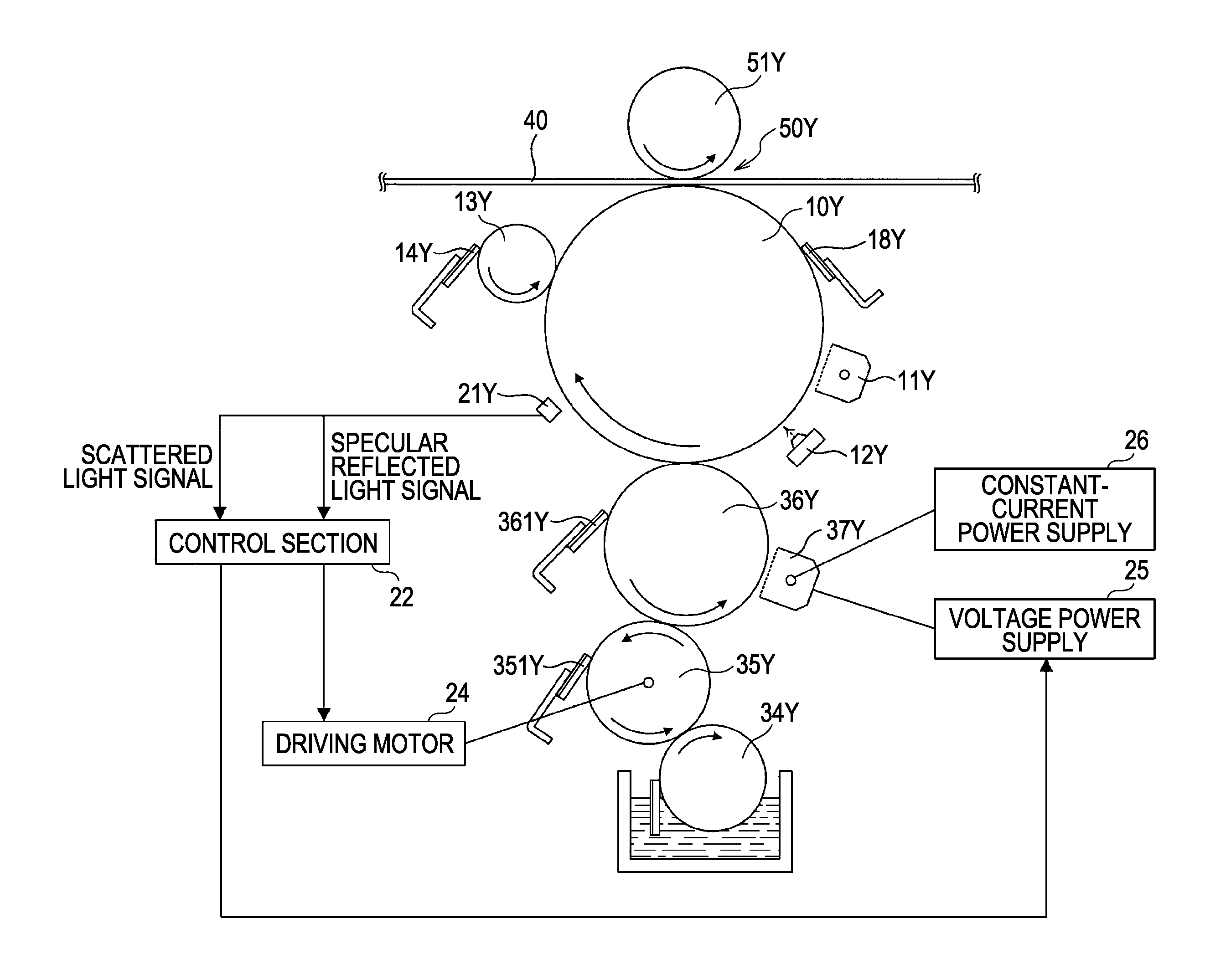
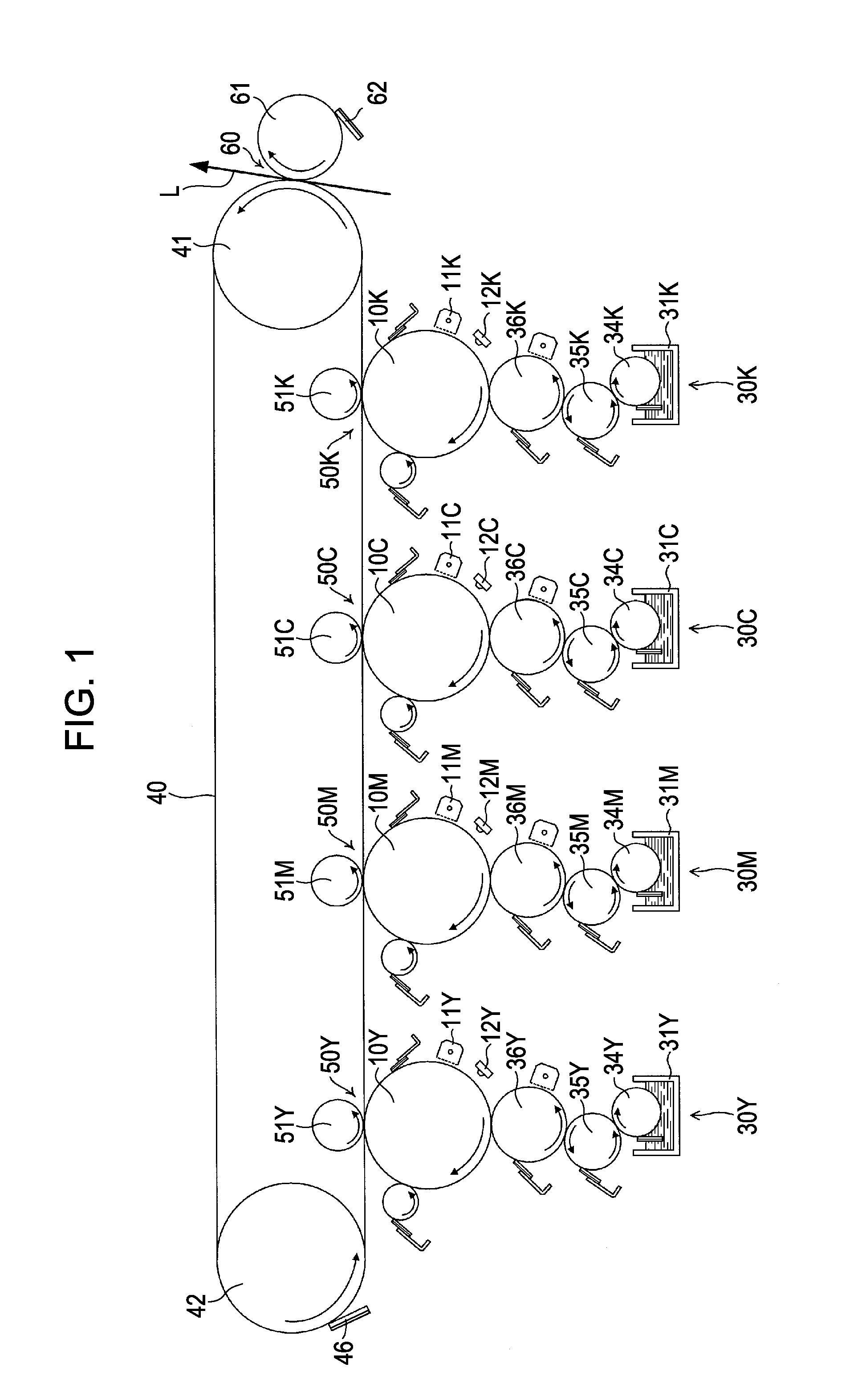
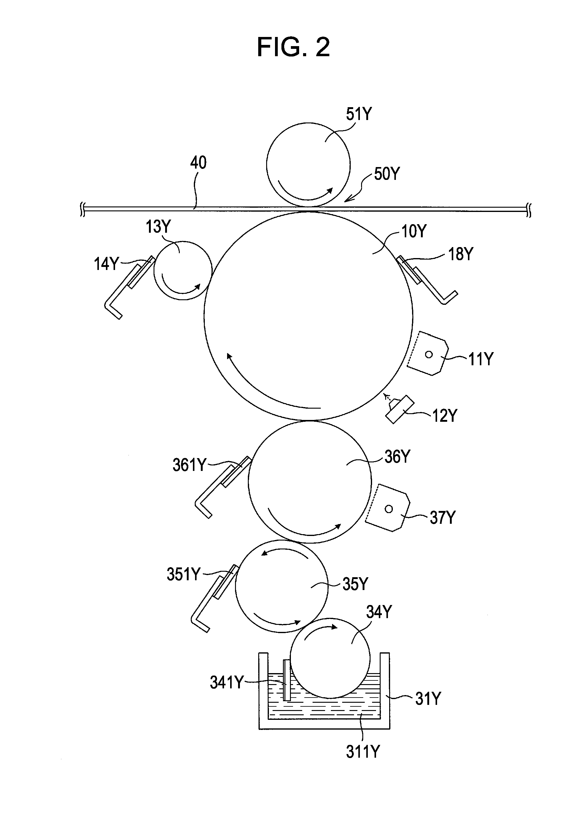
[0034]Hereinafter, embodiments of the invention will be described with reference to the drawings. FIG. 1 is a diagram illustrating main the constituents of the image forming apparatus according to the embodiment of the invention. With respect to an image forming section disposed in the central portion of the image forming apparatus, four developing devices 30Y, 30M, 30C, and 30K are disposed in the lower portion of the image forming section, and an intermediate transfer body 40 and a secondary transfer section (secondary transfer unit 60) are disposed in the upper portion of the image forming section. Hereinafter, the image forming section and the developing devices 30Y, 30M, 30C, and 30K will be described. However, since the constitutions of each color are identical to each other, the description is made with the subscript alphabets which signify the colors being omitted. Meanwhile, since the image forming apparatus according to the embodiment is configured to be capable of forming...


PUM


Abstract

An image forming method is provided, which includes: adjusting the amount of application of liquid developer to an image carrier from a developer carrier in response to an output signal of a first light receiving section obtained by emitting light to a first image carried in the image carrier; and adjusting a bias applied to a charging member which is disposed in the developer carrier in response to an output signal of a second light receiving section obtained by emitting light to a second image different from the first image carried in the image carrier.

Description

BACKGROUND[0001]1. Technical Field[0002]The present invention relates to an image forming apparatus and an image forming method which perform image formation by developing an electrostatic latent image formed on an image carrier by liquid developer having toner and carrier liquid, and transferring and fixing a developed developer image to a recording material.[0003]2. Related Art[0004]Various image forming apparatuses have been proposed in which electrostatic latent images are developed and visualized using high-viscosity liquid developer where toner composed of solid components is dispersed in a liquid solvent used as a carrier liquid. The developer used in the image forming apparatuses is an agent where solid components (toner particles) are suspended in an electrically isolating high-viscosity organic solvent (carrier liquid) composed of silicon oil, mineral oil, cooking oil or the like. Extremely fine particles of which the particle diameter is 1 μm or so are used as the toner p...

Claims


Application Information

Patent Timeline
Patent Type & Authority Applications(United States)
IPC IPC(8): G03G15/10
CPCG03G15/104G03G15/5037G03G2215/00042
Inventor FUKAZAWA, MASAHIRO
Owner SEIKO EPSON CORP
Why Eureka
Try Eureka