Image forming apparatus

a technology of forming apparatus and forming tube, which is applied in the direction of electrographic process apparatus, instruments, optics, etc., can solve the problem of uneven images and achieve the effect of suppressing uneven images

Inactive Publication Date: 2014-05-13
CANON KK
View PDF7 Cites 0 Cited by
  • Summary
  • Abstract
  • Description
  • Claims
  • Application Information

AI Technical Summary

Benefits of technology

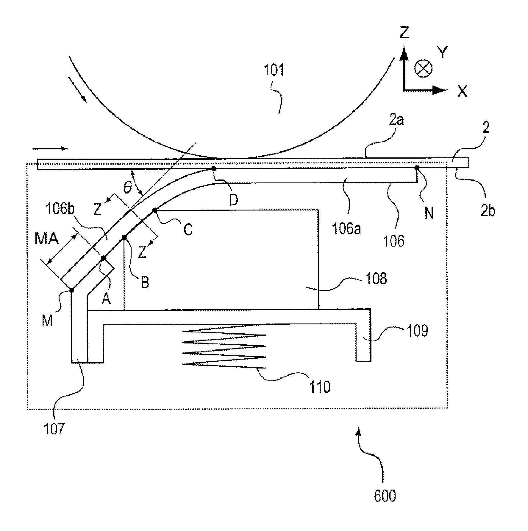
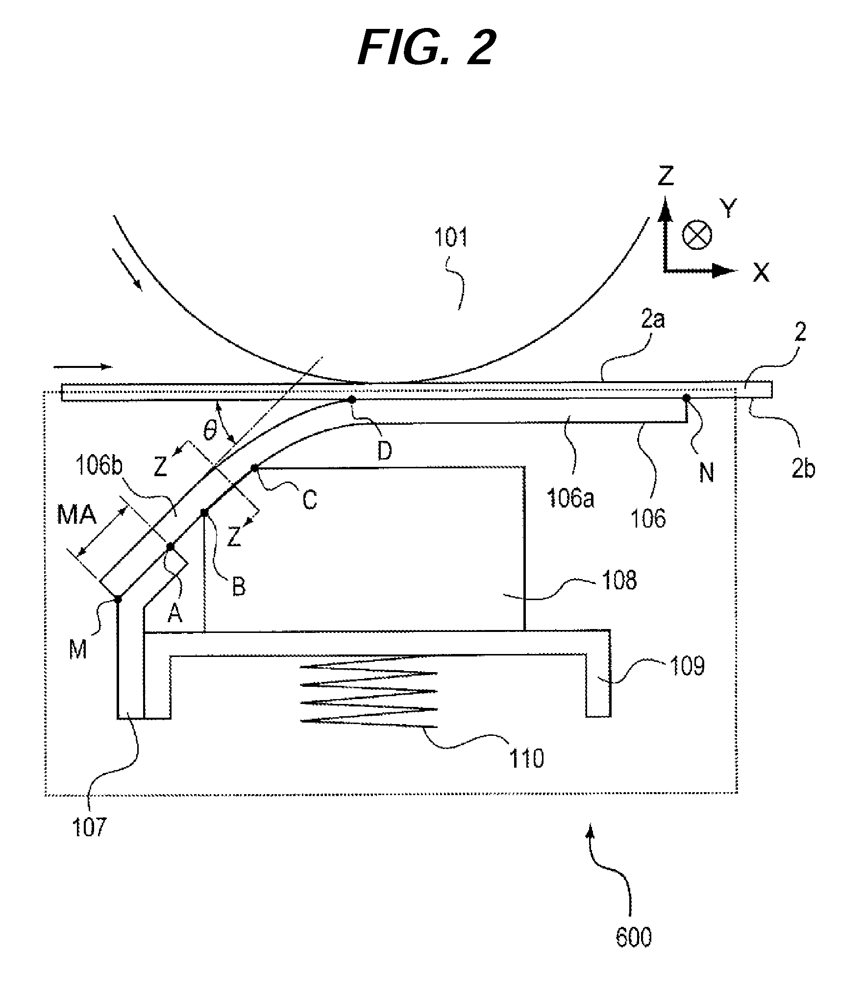
[0008]In view of the aforementioned circumstances, the present invention provides an image forming apparatus enabling suppression of uneven images by making a charge applied from a conductive member to a belt uniform in a direction parallel to a direction of an axis of an image bearing member.

Problems solved by technology

Consequently, unevenness occurs in supply of charge from the conductive member, resulting in uneven images.

Method used


Image

  • Image forming apparatus
  • Image forming apparatus
  • Image forming apparatus

Examples


embodiment 2

[0061]The present embodiment is the same as the image forming apparatus 500 according to embodiment 1 except change of the primary transfer device 600 in each station to primary transfer devices 700. Therefore, the primary transfer device 700, which is a point of difference from embodiment 1, will be described with reference to FIG. 4.

[0062]FIG. 4 is a cross-sectional diagram illustrating a configuration of a primary transfer device 700 included in an image forming apparatus according to embodiment 2. Components of the primary transfer device 700 according to the embodiment 2 that are the same as those of the primary transfer device 600 according to embodiment 1 are provided with the same reference numerals and a description of such components and effects thereof will be omitted as appropriate. Since embodiment 2 can be applied to an image forming apparatus similar to that of embodiment 1, a description of the image forming apparatus will be omitted. The primary transfer device 700 ...


PUM


Abstract

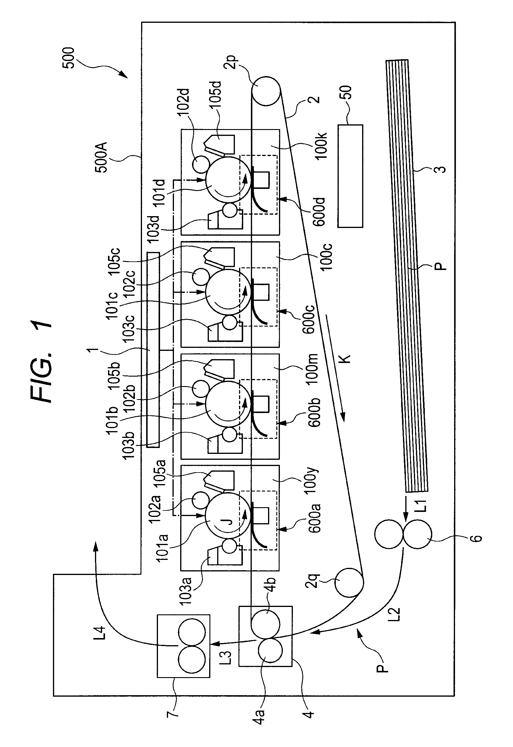
An image forming apparatus includes an image bearing member that carries a toner image, a rotatable endless belt facing the image bearing member, and a transfer device arranged on an inner peripheral side of the belt and transferring a toner image from the image bearing member to the belt. The transfer device includes a sheet member having conductivity and having a free end and an opposite end which is fixed. In addition, a support member supports and contacts the sheet member, and a securing member secures the sheet member. The sheet member at least has a first region secured by the securing member, a second region in contact with the support member, a third region separated from the support member and the belt, and a fourth region separated from the support member and in contact with the belt. The first region, the second region, the third region and the fourth region are located in order from an upstream side toward a downstream side in a rotational direction of the belt.

Description

BACKGROUND OF THE INVENTION[0001]1. Field of the Invention[0002]The present invention relates to an image forming apparatus in which a toner image is transferred to a transfer material.[0003]2. Description of the Related Art[0004]There are known image forming apparatuses including a primary transfer device that electrostatically transfers a toner image carried on a surface of an image bearing member to a belt. As an example of such primary transfer device, there is a known device including a transfer member that forms a transfer electric field while being rubbed against a belt in a secured state as opposed to a device that rotates like a primary transfer roller. Japanese Patent Application Laid-Open No. H11-143249 discloses an invention relating to such type of primary transfer device.[0005]The invention disclosed in Japanese Patent Application Laid-Open No. H11-143249 relates to a primary transfer device including a sheet-like conductive member that is in contact with a belt, a PET...

Claims


Application Information

Patent Timeline
Patent Type & Authority Patents(United States)
IPC IPC(8): G03G15/14
CPCG03G2215/0132G03G15/1605G03G2215/1633G03G15/1685
Inventor KUDO, YOSHIKI
Owner CANON KK
Why Eureka
Try Eureka