Optical print head and image forming apparatus

a printing head and optical technology, applied in the field of optical printing head and image forming apparatus, can solve the problems of complex wiring configuration, high manufacturing cost, uneven light emission amount due to the potential drop,

Active Publication Date: 2016-10-11
KONICA MINOLTA INC
View PDF17 Cites 1 Cited by
  • Summary
  • Abstract
  • Description
  • Claims
  • Application Information

AI Technical Summary

Benefits of technology

[0007]According to this configuration with an increased number of feeding points, it is possible to suppress voltage variation of the power line from influencing the light-emitting elements. In other words, it is possible to shorten a length from one feeding point to each of the light-emitting elements compared with the case where a less number of feeding points are provided such as a case where no auxiliary power line is provided. This decreases a potential drop due to a wiring resistance. As a result, it is possible to decrease a difference in drive current to be supplied between the light-emitting elements caused by the potential drop, thereby to decrease a difference in light emission amount between the light-emitting elements. This suppresses image unevenness due to the difference in light emission amount.

Problems solved by technology

However, another problem occurs in the configuration disclosed in Patent Literature 1.
This complicates a wiring configuration and requires a high manufacturing cost.
Accordingly, a problem still remains that unevenness in light emission amount due to the potential drop is not sufficiently eliminated.
However, another problem is caused by the above method.
This results in a short operating life of the light-emitting elements.

Method used


Image

  • Optical print head and image forming apparatus
  • Optical print head and image forming apparatus
  • Optical print head and image forming apparatus

Examples


embodiment

(1) Configuration of Printer 1A

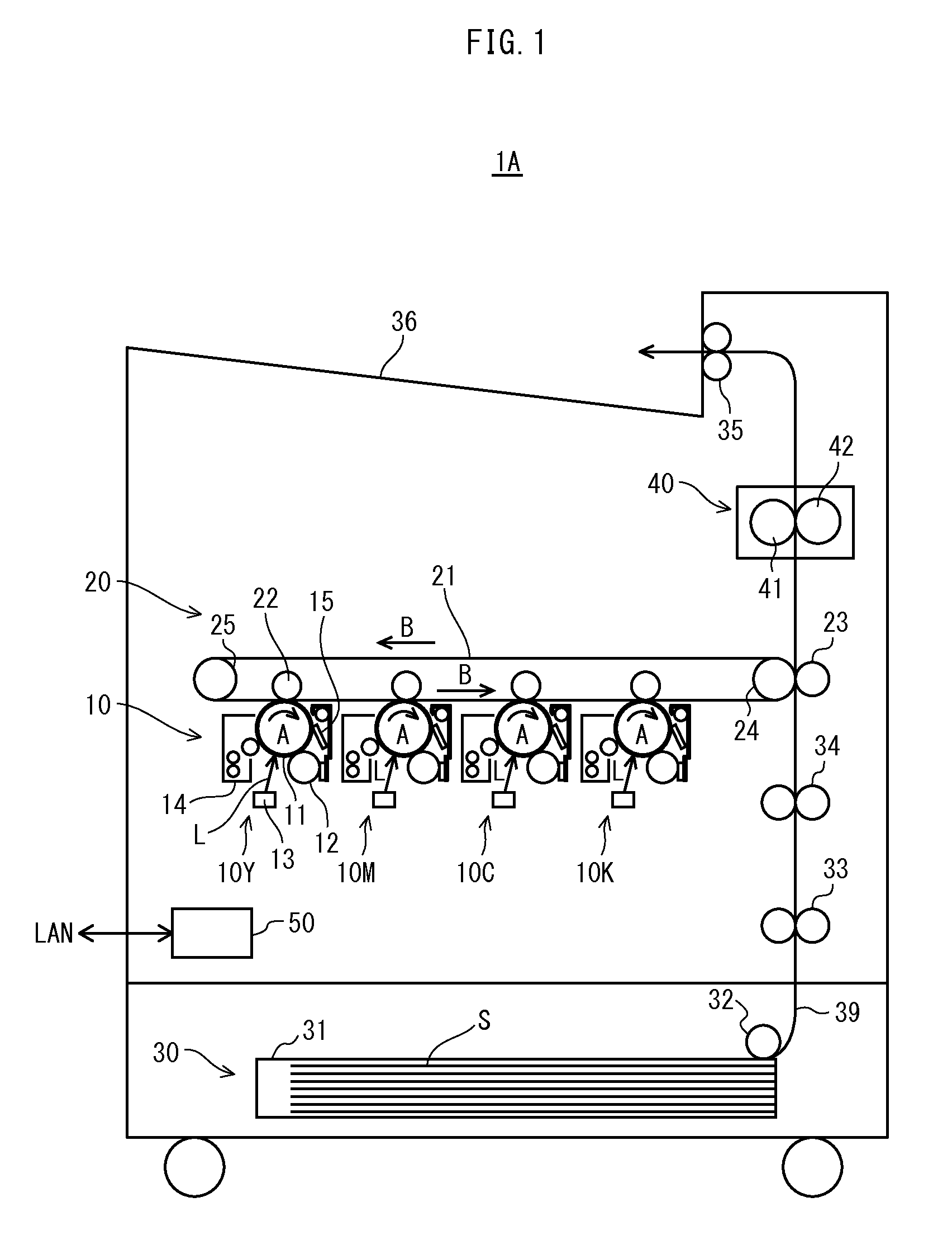
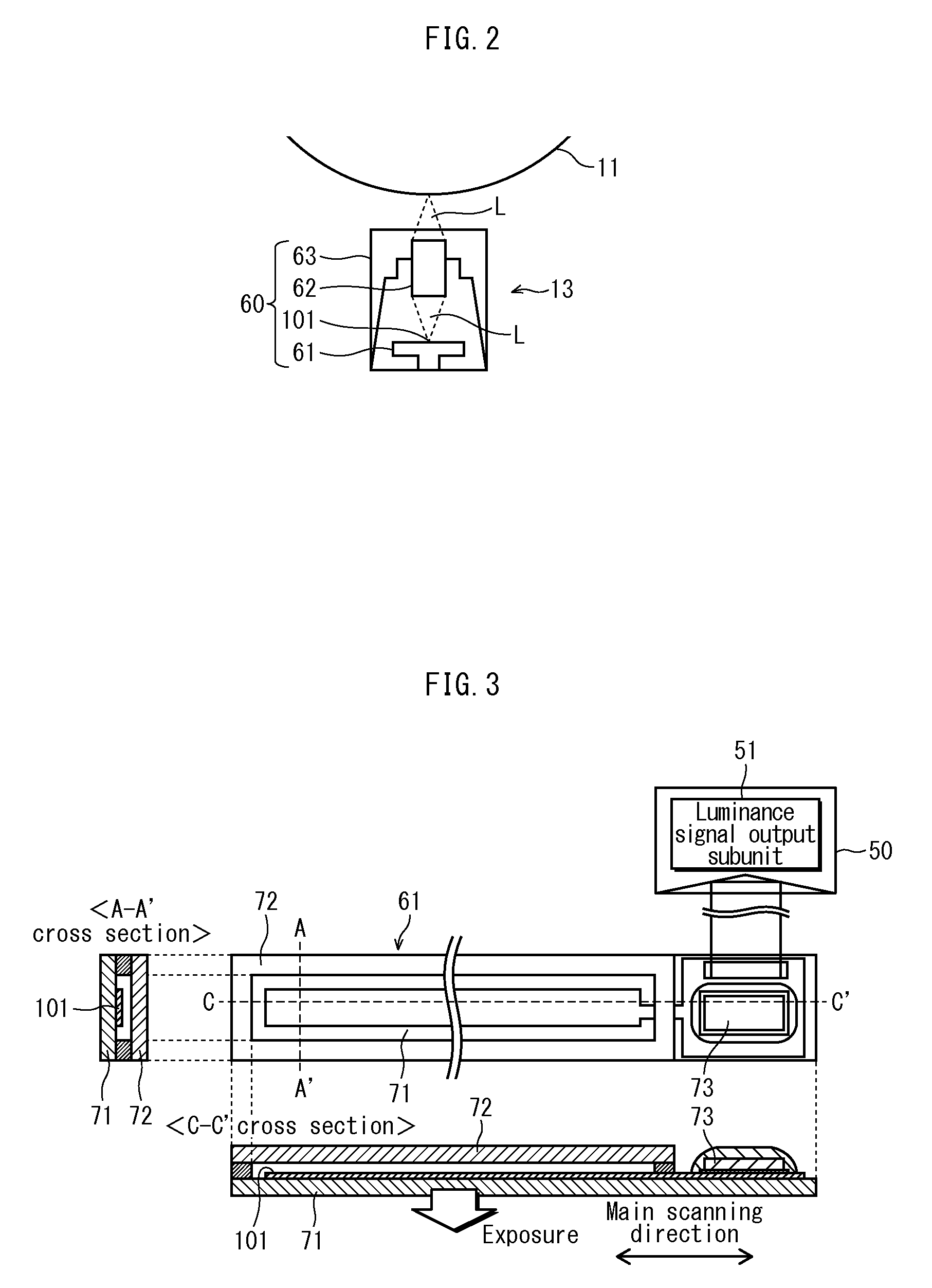
[0029]FIG. 1 shows the overall configuration of a printer 1A relating to the present embodiment. As shown in the figure, the printer 1A forms images by an electronic photography system, and includes an image process unit 10, a sheet feeding unit 30, a fixing unit 40, and a control unit 50.

[0030]The printer 1A is connected with a network such as LAN to receive a print instruction from an external terminal device (not illustrated) or an operation panel including a display unit (not illustrated). Upon receipt of such a print instruction, the printer 1A forms respective toner images of yellow, magenta, cyan, and black colors, and sequentially multi-transfers the toner images to a recording sheet, such that a full-color image is formed on the recording sheet to complete a print operation. In the following description, the reproduction colors of yellow, magenta, cyan, and black are denoted as Y, M, C and K, respectively, and any compositional element related...


PUM


Abstract

An optical print head includes: light-emitting elements in line shape; first power line supplying first reference voltage; second power line supplying drive current to each light-emitting element and supplying second reference voltage; DAC outputting first voltage indicating light emission amount of each light-emitting element; first elements for holding first voltage difference between the first reference voltage and the first voltage; second elements each electrically connectable with corresponding first element and for holding second voltage difference between the second reference voltage and second voltage according to the first voltage, and during supply of drive current, controls each first element to hold the first difference by electrically disconnecting the first and second elements, and temporarily suspends supply of the drive current, and controls the second element to hold the second difference by electrically connecting the first and second elements, such that the drive current according to the second voltage difference is supplied.

Description

CROSS-REFERENCE TO RELATED APPLICATIONS[0001]This application is based on application No. 2014-147545 filed in Japan, the contents of which are hereby incorporated by reference.BACKGROUND OF THE INVENTION[0002](1) Field of the Invention[0003]The present invention relates to an optical print head (PH) that performs writing onto a photoreceptor by an optical beam and an image forming apparatus including the optical PH.[0004](2) Related Art[0005]With a recent increase demand for size-reduction of optical PHs that perform writing onto a photoreceptor by an optical beam that are included in image forming apparatuses such as printers, there have been increasingly used optical PHs in which micro dot light-emitting elements are disposed in a line shape.[0006]For example, Patent Literature 1 (Japanese Patent Application Publication No. 2005-144686) discloses an optical PH that has a configuration in which a plurality of light-emitting elements (organic EL elements), a first power line, and a...

Claims


Application Information

Patent Timeline
Patent Type & Authority Patents(United States)
IPC IPC(8): G03G15/00G03G15/04G03G15/043
CPCG03G15/04054G03G15/043
Inventor OBAYASHI, MAKOTOMASUDA, SATOSHIWATANABE, YOSHIKAZUIIJIMA, MASAYUKIYANO, SOUEMURA, TAKAKI
Owner KONICA MINOLTA INC
Why Eureka
Try Eureka