
Developing device and image forming apparatus

a technology of developing device and image forming apparatus, which is applied in the direction of electrographic process apparatus, instruments, optics, etc., can solve the problems of image unevenness, particularly prone to occur for the developing roller that rotates at a high speed, image unevenness, etc., to suppress image unevenness, improve agitation and mixture, and high image quality

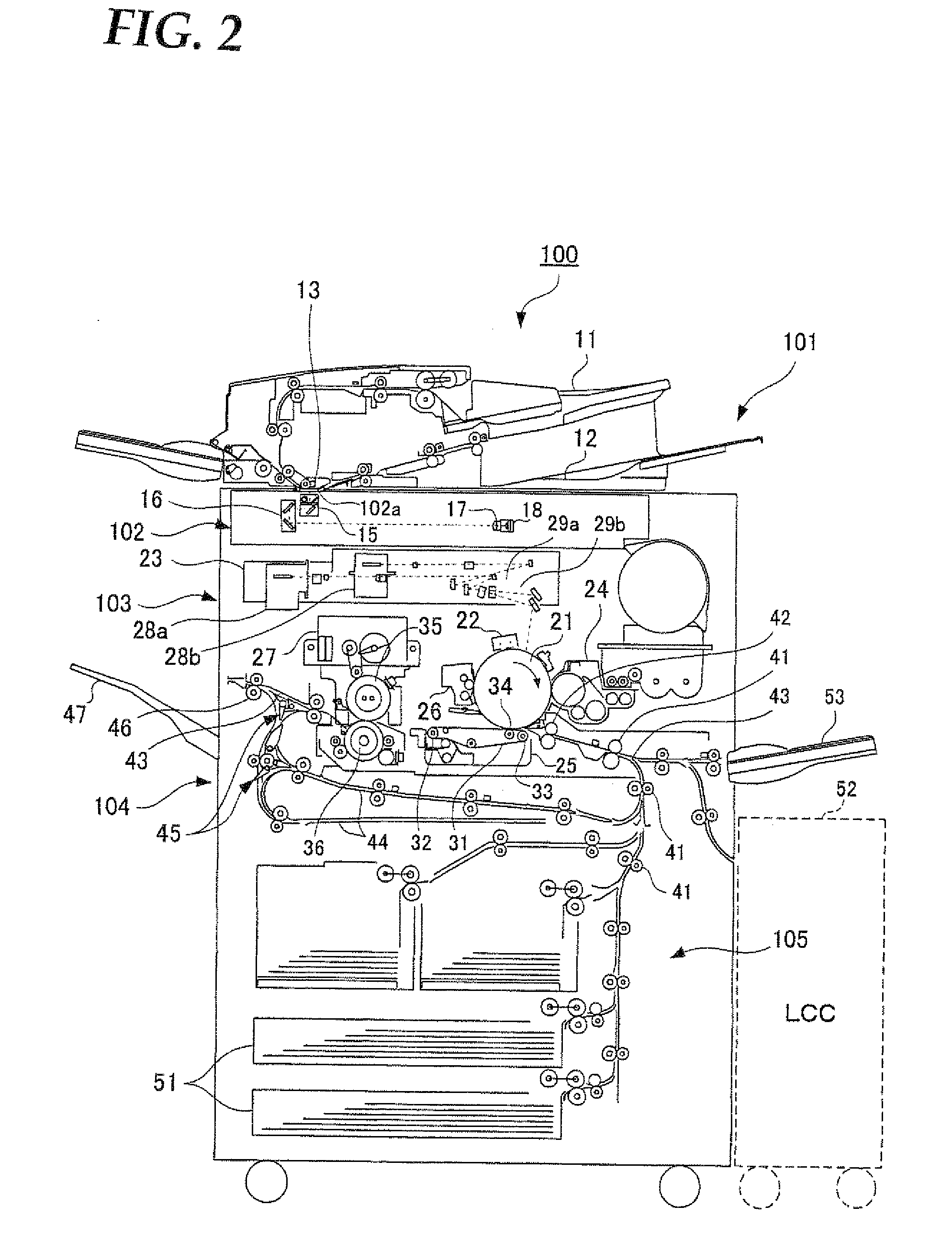
Active Publication Date: 2009-12-31
SHARP KK
View PDF11 Cites 0 Cited by
  • Summary
  • Abstract
  • Description
  • Claims
  • Application Information

AI Technical Summary

Benefits of technology

[0013]The present invention has been devised in view of the above problems entailing the conventional developing devices, it is therefore an object of the present invention to provide a novel and improved developing device and image forming apparatus with which a dual-component developer of uniform toner concentration across the length of the developing roller can be quickly supplied.

Problems solved by technology

In recent high-speed digital multi-functional machines, there are cases that image unevenness occurs when printing of the same print pattern has been continuously performed.
This problem is particularly prone to occur for the developing roller that rotates at a high speed.
For example, when print patterns having a black solid area in the central part have been continuously printed, the toner concentration of the developer has become lowered in the center across the length of the developing roller, hence causing image unevenness such that the necessary print density cannot be obtained.
As a result, there occurs a large difference in the toner concentration of the dual-component developer between before and after it is agitated and mixed in the agitating roller area, hence the toner concentration will remain uneven across the length of the developing roller even when the developer is supplied to the developing roller.
Also, when print patterns having gradually changing printing ratios along the longitudinal direction of the developing hopper have been continuously printed, the toner concentration becomes different between the far and near sides across the length of the developing roller, hence making the images uneven or different in print density.
As a result, there occurs a large difference in the toner concentration of the dual-component developer between before and after it is agitated and mixed in the agitating roller area, hence the toner concentration will similarly remain uneven across the length of the developing roller when the developer is supplied to the developing roller.
However, the developing device disclosed in the aforementioned patent document 1 is constructed to focus on crushing toner aggregations, but the toner concentration across the length of the developing roller is not taken into consideration.
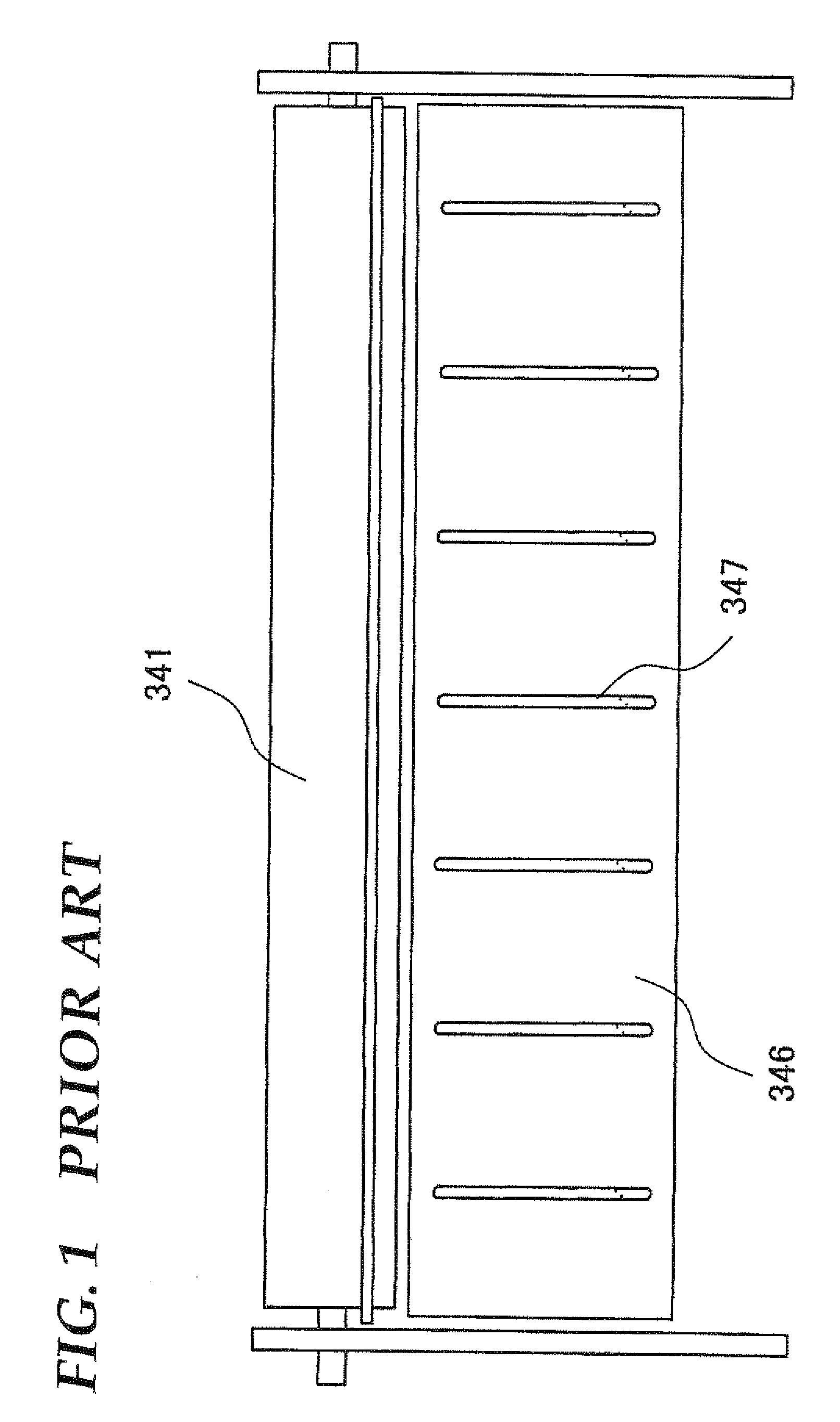
Further, since this configuration takes such a structure that the developer is dropped through one place into the developing hopper, there has been the problem that it takes long time to make the toner concentration uniform.

Method used


Image

  • Developing device and image forming apparatus
  • Developing device and image forming apparatus
  • Developing device and image forming apparatus

Examples


examples 4 to 6

[0099]In examples 4 to 6, continuous printing tests of 500 sheets were performed using a print pattern A having 12.5% black solid area in an A4-sized document, in the same manner as in examples 1 to 3, except that the rotational speed of developing roller 241 was set at 864 mm / sec, developing roller 241 was continuously driven for 30 min (example 4) or for 60 min (examples 5 and 6), and the printing operation was suspended every 15 minutes and ten reciprocating movements of the partitioning ribs were added. After the continuous printing, the developer in the upper part of toner agitation roller 244b was sampled to measure toner concentration. Further, evaluation on the image quality at the end of printing was made similarly to examples 1 to 3 by evaluating the variation of the printed density at the center (C). In example 6, no reciprocating movement of the partitioning ribs was added.

[0100]The results of the above examples and comparative examples will be described.

[0101]As to eval...


PUM


Abstract

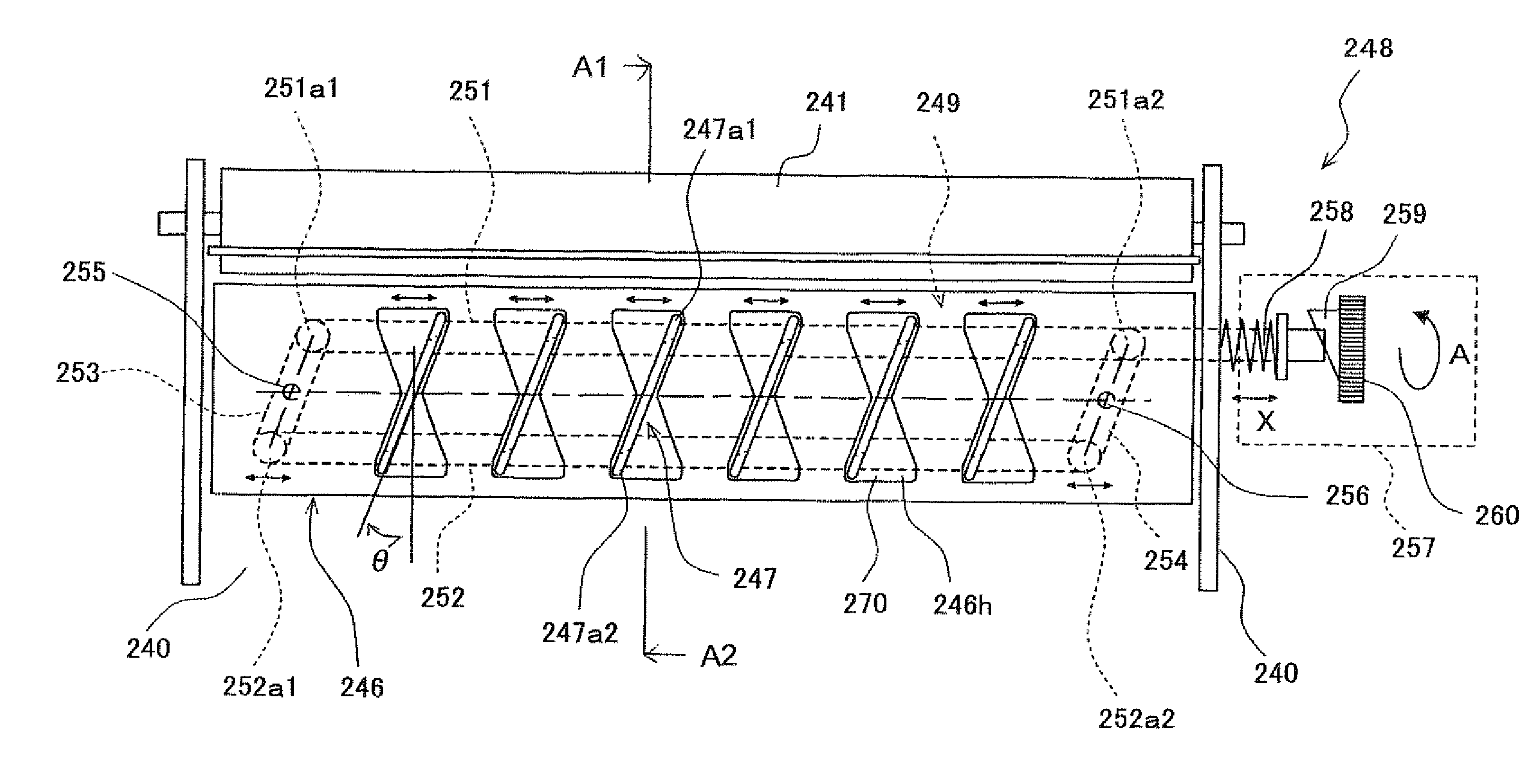
A developing device for developing an electrostatic latent image formed on an photoreceptor drum with a dual-component developer, includes: a developing hopper for storing the developer; an agitation roller for conveying the developer while agitating; a developing roller which supplies the developer to a developing area located opposing the photoreceptor drum; a layer thickness-regulating member for regulating the layer thickness of the developer being conveyed by the developing roller; a flow-guide plate for flowing down the surplus developer that was rejected to a position away from the layer thickness-regulating member; a multiple number of partitioning ribs arranged upright on the flow-guided plate for flowing down the surplus developer in a predetermined direction whilst diffusing the developer with respect to the longitudinal direction of the developer roller; and a downflow direction control mechanism for controlling the downflow direction of the surplus developer regulated by the partitioning ribs.

Description

[0001]This Nonprovisional application claims priority under 35 U.S.C. §119(a) on Patent Application No. 2008-171195 filed in Japan on 30 Jun. 2008, the entire contents of which are hereby incorporated by reference.BACKGROUND OF THE INVENTION[0002](1) Field of the Invention[0003]The present invention relates to a developing device and an image forming apparatus for visualizing an electrostatic latent image formed on a photoreceptor etc. with a developer, in particular relating to a developing device and an image forming apparatus including an agitating mechanism for dual-component developer composed of toner and carrier.[0004](2) Description of the Prior Art[0005]The developing device using a dual-component developer in an image forming apparatus such as a digital multifunctional machine or the like incorporates a developing roller opposing a photoreceptor, an agitating roller and a toner supply and agitation roller, all being arranged rotatably in the developing hopper. Formed over ...

Claims


Application Information

Patent Timeline
Patent Type & Authority Applications(United States)
IPC IPC(8): G03G15/09
CPCG03G2215/0805G03G15/0815
Inventor AKEDO, SHUICHI
Owner SHARP KK
Learn More