Fluid turbine

a technology of flue gas turbine and turbine blade, which is applied in the direction of propellers, propulsive elements, water-acting propulsive elements, etc., can solve the problems of reducing efficiency, design that has not found favour for wind generation, and reducing efficiency, so as to reduce the drag effect of the other two blades and the maximum drag or momentum change

Inactive Publication Date: 2010-11-04
SUN YI +1
View PDF15 Cites 5 Cited by
  • Summary
  • Abstract
  • Description
  • Claims
  • Application Information

AI Technical Summary

Benefits of technology

[0015]An embodiment of a three-bladed design is shown in FIG. 3a and FIG. 3b, where the fluid flow direction z is presented vertically to the page as shown and the mill blades turn in the clockwise direction. The blade 7 on the left (FIG. 3a) provides maximum drag or momentum change effect, while the drag effect of the other two blades is much reduced so that there is greater net force acting on the left of the mill than the right, so causing rotation. There will also be a lift force contribution dependent on the blade angle φ at intermediate positions. Since the degree to which l

Problems solved by technology

However, during a full rotation cycle the cups produce significant drag on the return half of the cycle and therefore the efficiency is reduced.
For this reason, such designs have not found favour for wind generation schemes, although their simplicity makes them ideal for use as anemometers for example where power efficiency is not an important consi

Method used


Image

  • Fluid turbine
  • Fluid turbine
  • Fluid turbine

Examples


Embodiment Construction

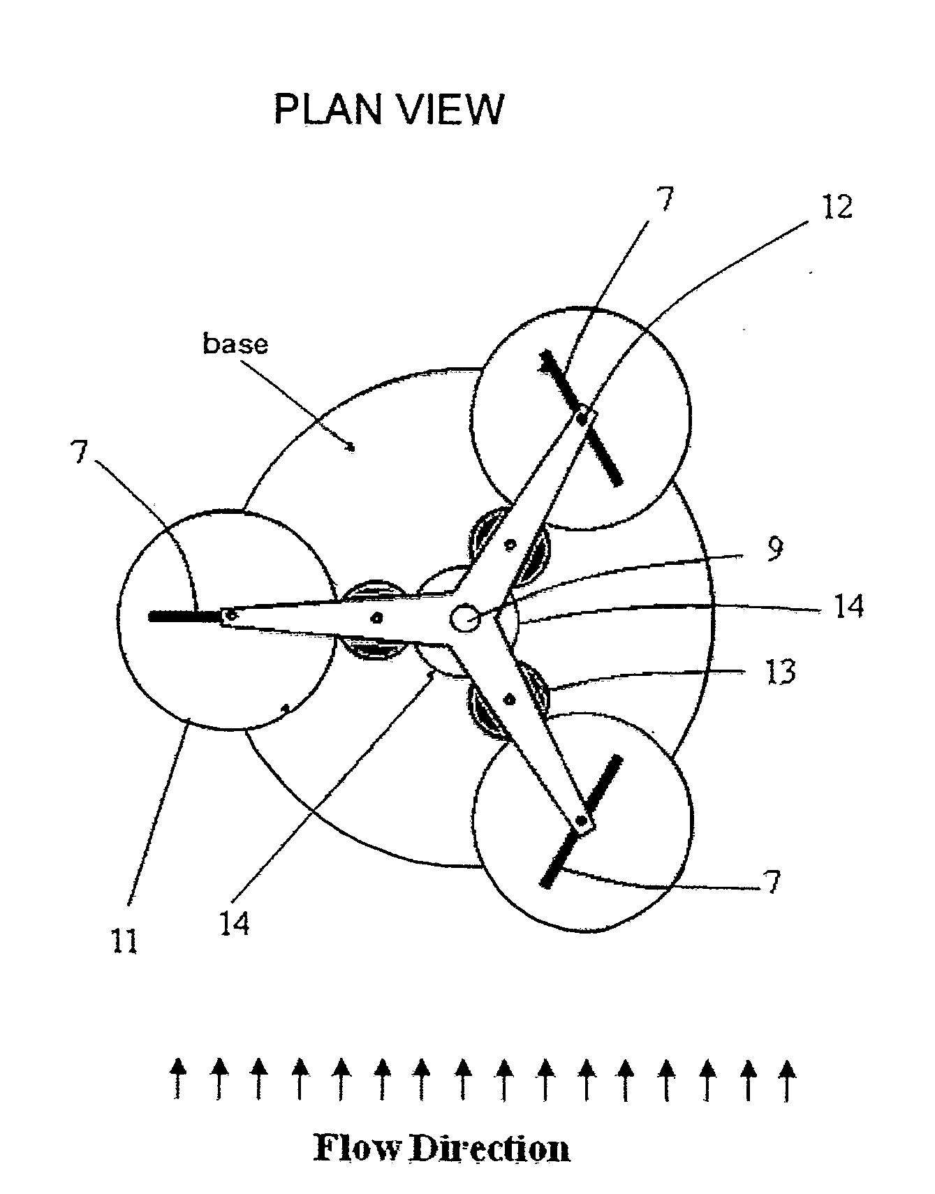
[0031]Referring to FIGS. 3a and 3b, the turbine blade 7 is fixed by its spindle 12 to top and bottom plates 10 where the axis is located by holes in the plates through which the spindle passes. A gear 11 is fixed to the spindle 12. A gear set 13 is allowed to freely rotate about a spindle 8 fixed to the bottom plate 10. This gear set meshes with gear 11. Gear 14 is fixed to a cylindrical outer spindle 15 which is also fixed to a base 16. Gear set 13 also meshes with gear 14 which may be eccentrically mounted or non-circular. Gear set 13 comprises either one or two gears fixed on the same spindle and rotate together such that a top gear meshes with gear 11 and a bottom gear meshes with gear 14 or vice versa. The two gears comprising set 13 may be different diameters or one or both may be eccentrically mounted or non-circular. The gear set comprising 11, 13 and 14 acts such that when the spindle 12 is rotated about the central axis 9, the blade rotates about its axis 12 within the dom...


PUM


Abstract

A turbine for extracting power from a flowing fluid comprises a blade for interaction with the fluid, the blade being rotatable both about a primary axis and a blade axis. The blade axis is proximate to the blade, substantially parallel to the primary axis and spaced therefrom. Rotation actuating means is provided to rotate the blade about the blade axis in dependence upon the rotation of the blade about the primary axis such that the rotation angle of the blade about the blade axis is a function of the rotation angle of the blade about the primary axis. The rotation of the blade about the blade axis is in the same direction of rotation as the blade axis about the primary axis.

Description

FIELD OF THE INVENTION[0001]This invention relates to the extraction of power from a flowing fluid by means of a bladed turbine. Such a turbine may be used to generate electrical energy from fluid flow such as river water flow, tidal water flow or from wind.BACKGROUND OF THE INVENTION[0002]Various devices used in the extraction of energy are known in the art using two basic mechanisms: these are variously denoted by; i) “drag” or “momentum transfer” or “momentum reversal” and ii) by “lift”. Known devices typically use one or other of these mechanisms. Momentum transfer systems rely on the fluid flow pushing against a vane, paddle or blade so that the vane is pushed in the same direction as the flow. A well-known example of a momentum transfer type device is the Pelton Wheel. However, during a full rotation cycle the cups produce significant drag on the return half of the cycle and therefore the efficiency is reduced. For this reason, such designs have not found favour for wind gener...

Claims


Application Information

Patent Timeline
IPC IPC(8): B64C27/00B64C11/00
CPCF03D3/068F05B2200/20F05B2210/16Y02E10/38Y02E10/28Y02E10/74F05B2260/72Y02E10/30F03B17/067F04D29/18Y02E10/20
Inventor JANSSEN, ADRIAN
Owner SUN YI
Why Eureka
Try Eureka