Pointer detection apparatus and pointer detection method

a detection apparatus and pointer technology, applied in the field of pointer detection apparatus and pointer detection method, can solve the problems of inconvenient practical use of the pointer detection apparatus described above, long time-consuming and laborious detection at all cross points, etc., and achieve the effect of speeding up

Active Publication Date: 2010-12-23
WACOM CO LTD
View PDF52 Cites 50 Cited by
  • Summary
  • Abstract
  • Description
  • Claims
  • Application Information

AI Technical Summary

Benefits of technology

[0016]Therefore, it is an object of the present invention to provide a pointer detection apparatus and a pointer detection me

Problems solved by technology

Since such a pointer detection apparatus of the cross point type electrostatic coupling system as described above carries out a position detection process of cross points one by one per every p

Method used


Image

  • Pointer detection apparatus and pointer detection method
  • Pointer detection apparatus and pointer detection method
  • Pointer detection apparatus and pointer detection method

Examples


first embodiment

1. First Embodiment

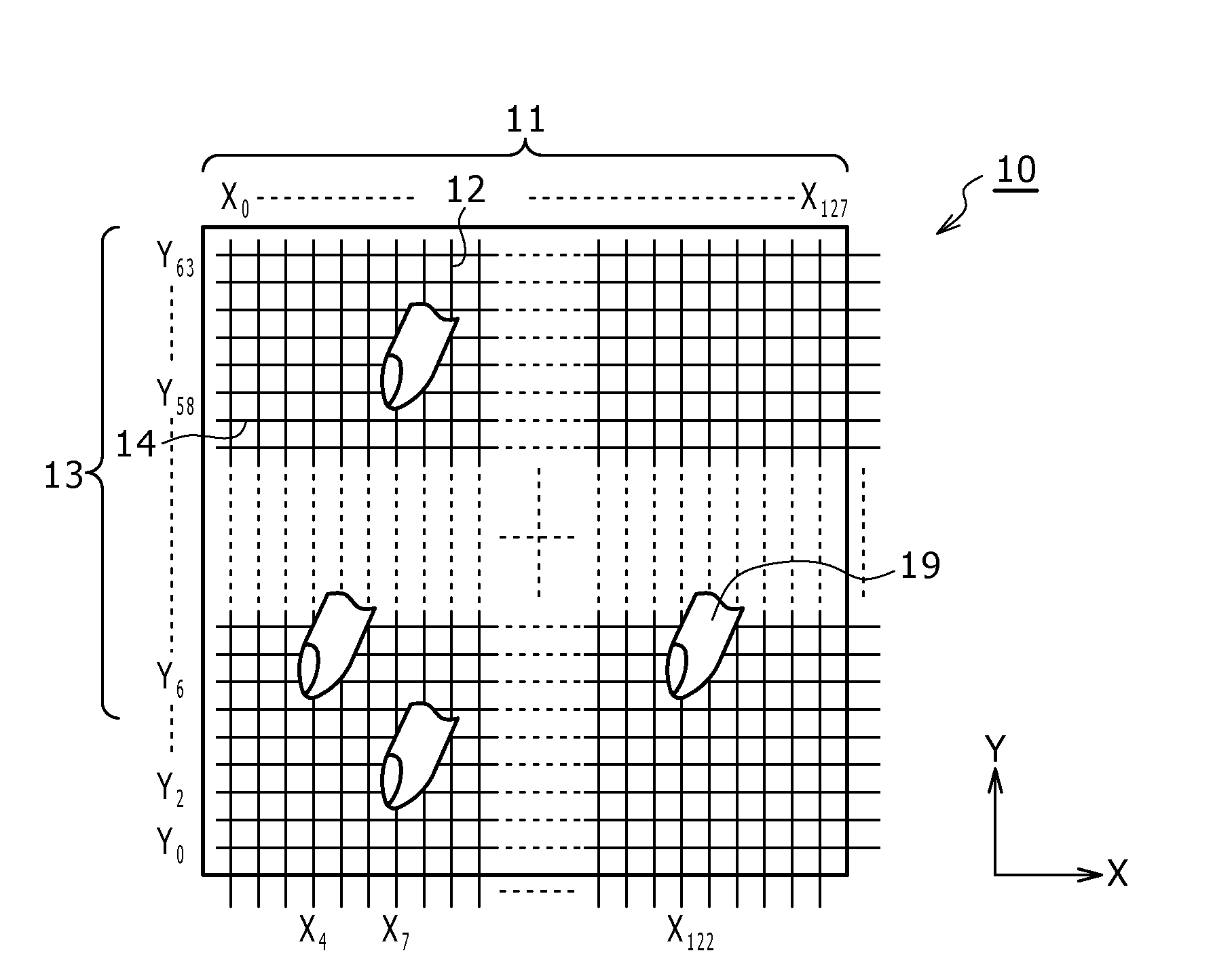
[0086]A first embodiment of the present invention relates to a basic configuration of a pointer detection apparatus and a pointer detection method of the present invention.

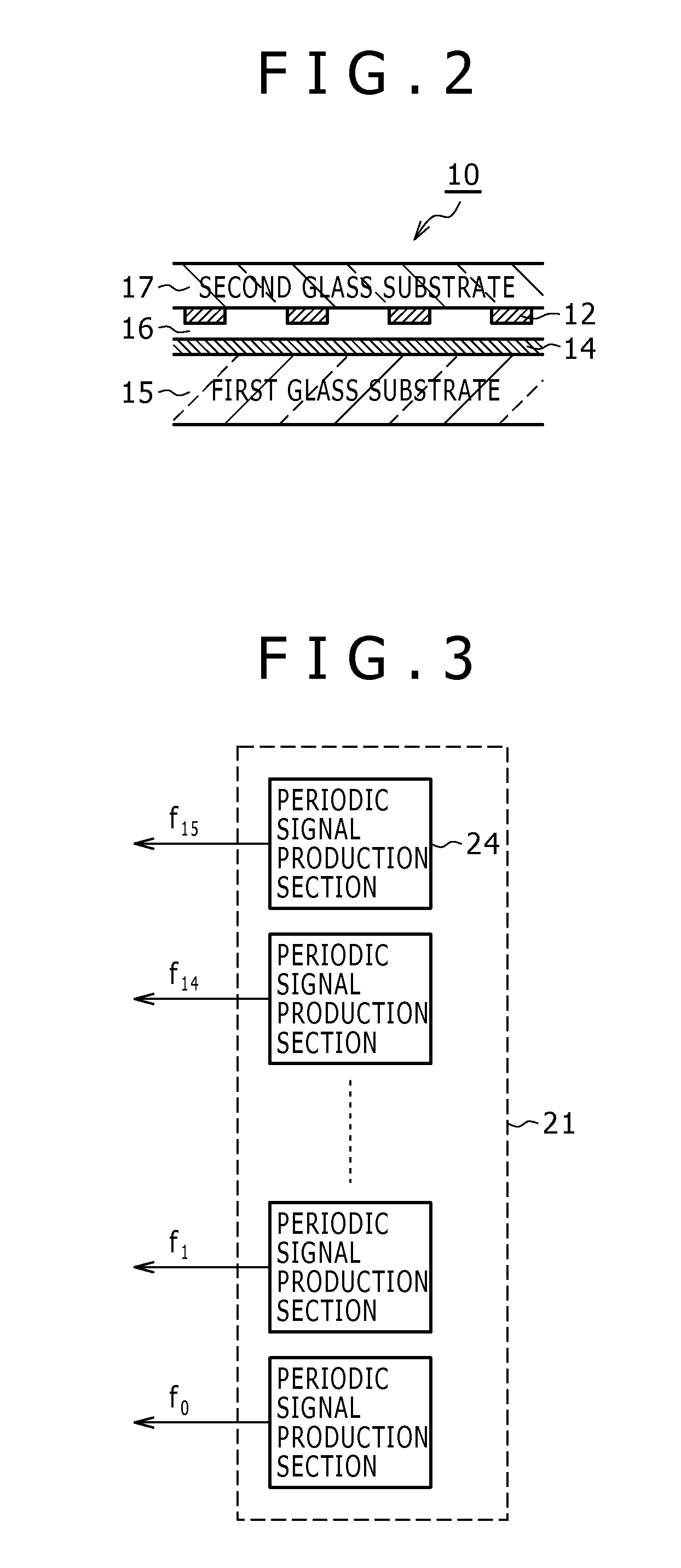
[0087]In the present embodiment, each of a transmission conductor group and a reception conductor group of a sensor section is divided into a plurality of groups, and signals in the form of periodic signals having frequencies different from each other among the different groups are supplied simultaneously, that is, multiplex transmitted. In the following description, the supplying form of signals in the present embodiment is referred to as “frequency multiplex system” or “frequency multiplex type,” and a plurality of periodic signals supplied are generally referred to as “multi-frequency signal.” The position detection system in the present invention is an electrostatic coupling system wherein the position of a pointer is detected based on a variation of the electrostatic coupling state between ...

second embodiment

2. Second Embodiment

Configuration of the Pointer Detection Apparatus

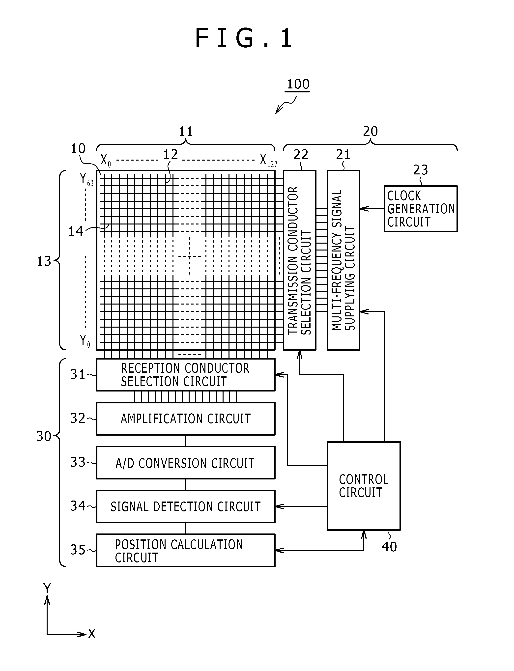
[0361]As described hereinabove in connection with the first embodiment and modifications 6 to 12 and 15 to 17 to the first embodiment, in the pointer detection apparatus of the present invention, periodic signals of different frequencies from each other can be supplied to a plurality of transmission conductors 14, and output signals from a plurality of reception conductors 12 can be input collectively to one amplifier. Further, a single pointer detection apparatus may selectively incorporate and switch between one or more configurations described above in connection with modifications 6 to 12 and 15 to 17, depending on each application, a required sensitivity, or the like. In particular, a single pointer detection apparatus may be configured to selectively vary the supplying form of periodic signals to the transmission conductor group 13 and the detection form of output signals from the reception conductor group 11 ...

third embodiment

3. Third Embodiment

[0396]In a third embodiment, another example of rotation of switching operation of transmission conductors 14 is used. The pointer detection apparatus of the third embodiment has the same configuration as that of the first embodiment, and therefore, overlapping description of the configuration is omitted herein to avoid redundancy.

[0397]The third embodiment is different from the first embodiment in that, while the rotation in the first embodiment is carried out such that each of the frequencies f0 to f15 supplied from the multi-frequency signal supplying circuit 21 is supplied to a fixed one of the transmission blocks 25, as seen in FIG. 5, the rotation in the third embodiment is carried out such that periodic signals to be supplied to transmission blocks may vary (i.e., each of the frequencies may be supplied to different transmission blocks). FIGS. 52A and 52B illustrate examples of the rotation of the switching operation of transmission conductors according to ...


PUM


Abstract

Disclosed herein is a pointer detection apparatus, including: a conductor pattern including a plurality of first conductors disposed in a first direction and a plurality of second conductors disposed in a second direction; a multi-frequency signal production circuit configured to produce a plurality of signals of different frequencies; a first conductor selection circuit configured to selectively supply the signals of different frequencies to those first conductors, between which N ones of the first conductors are interposed, N being a predetermined integer equal to or greater than 0; a second conductor selection circuit configured to selectively receive detection signals from the second conductors; and a signal detection circuit configured to obtain signals of individual frequencies, corresponding to the signals of different frequencies produced by the multi-frequency signal production circuit, which are representative of coupling states at cross points between the first conductors and the second conductors and are received from said second conductor selection circuit.

Description

CROSS-REFERENCE(S) TO RELATED APPLICATION(S)[0001]The present application claims priority under 35 U.S.C. §119 from Japanese Patent Application JP 2009-145879 filed in the Japanese Patent Office on Jun. 18, 2009, the entire content of which is incorporated herein by reference.BACKGROUND[0002]1. Field of the Invention[0003]This invention relates to a pointer detection apparatus and a pointer detection method, and more particularly to a pointer detection apparatus and a pointer detection method wherein the position of a pointer is detected by an electrostatic coupling system.[0004]2. Description of the Related Art[0005]Conventionally, for the detection of the position of a pointer such as a finger or a pen for use with a touch panel or a like apparatus, various systems have been proposed such as, for example, a resistive film system, an electrostatic coupling system, and an electrostatic capacity system. In recent years, a pointer detection apparatus including the electrostatic coupli...

Claims


Application Information

Patent Timeline
IPC IPC(8): G06F3/041
CPCG06F3/046G06F3/044G06F3/0446G06F3/0445G06F3/0448G06F2203/04111
Inventor ODA, YASUOSUGIYAMA, YOSHIHISA
Owner WACOM CO LTD
Why Eureka
Try Eureka