Information outlet

Inactive Publication Date: 2011-01-20
MATSUSHITA ELECTRIC WORKS LTD
View PDF2 Cites 3 Cited by
  • Summary
  • Abstract
  • Description
  • Claims
  • Application Information

AI Technical Summary

Benefits of technology

In view of above insufficiency, the purpose of the present invention has been aimed to provide an information outlet enabling a user to easily judge whether or not DC power is being supplied.
According to this invention, by means of watching the display unit provided to the case, a user can easily judge whether or not the DC power is being supplied.
According to this embodiment, the illuminant emits light while the DC power is supplied to the plug connection unit, and does not emit the light while the DC power is not supplied to the plug connection unit. Therefore, by means of watching the illuminant, a user can easily judge whether or not the DC power is being supplied. Further, the illuminant emits the light by use of the DC power supplied to the plug connection unit. In short, it is unnecessary to provide a power source configured to light the illuminant. It is possible to suppress the rise in a production cost.

Problems solved by technology

Accordingly, with reference to an exterior appearance of the information outlet, it is difficult to judge whether or not DC power is supplied to the terminal receiving member.
Therefore, when a user intends to connect a device to the information outlet having the terminal receiving member receiving DC power, the user is likely to mistakenly connect the device to the information outlet having the terminal receiving member not receiving DC power.

Method used


Image

  • Information outlet
  • Information outlet
  • Information outlet

Examples


first embodiment

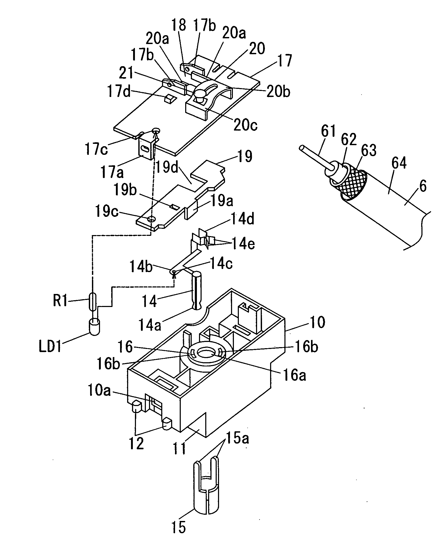
The information outlet 1 of the present embodiment is a TV outlet, for example. As shown in FIG. 9, the TV outlet is used for transmitting an electrical signal corresponding to a radio wave received by an antenna 3 placed outside the house H to a TV receiver or the like placed inside the house H. In the instance shown in FIG. 9, a receiving amplifier 4 configured to amplify the electrical signal from the antenna 3, and a distributor (external device) 5 configured to distribute the electrical signal to a plurality of the information outlets 1 are interposed between the antenna 3 and the information outlet 1. The antenna 3 is electrically connected to the receiving amplifier 4 by a coaxial cable 6, and the receiving amplifier 4 is electrically connected to the distributor 5 by a coaxial cable 6, and the distributor 5 is electrically connected to the information outlet 1 by a coaxial cable 6,

The coaxial cable 6 is adapted in use to transmit an audio signal, a video signal, or the like....

second embodiment

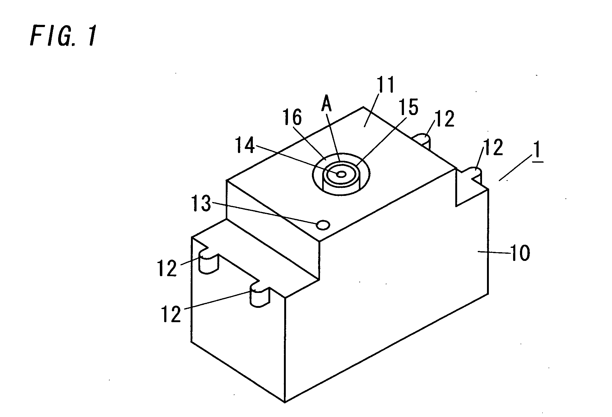
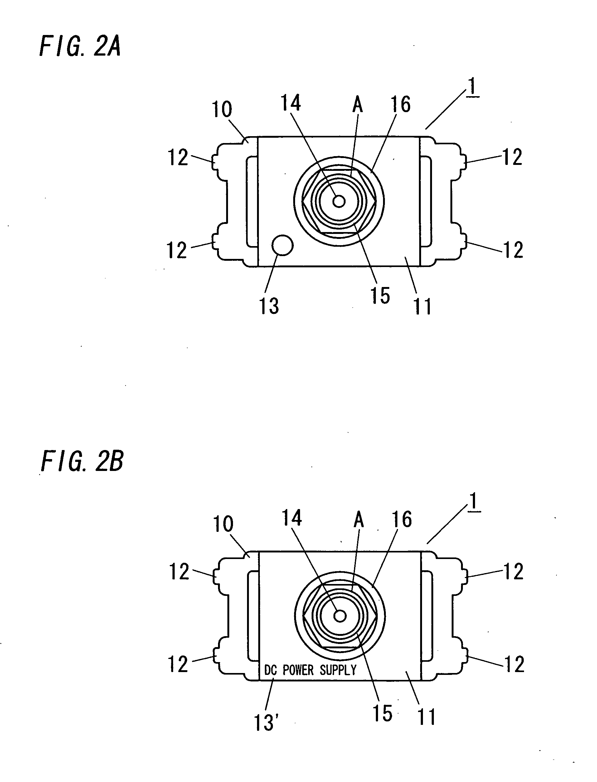
The information outlet 7 in accordance with the second embodiment is an information modular jack 7 for LAN, as shown in FIGS. 5 and 6. The information outlet 7 includes the housing (case) 10. The housing 10 is configured to house parts constituting a plug connection unit 8 shown in FIG. 8, three light emitting diodes (illuminants) LD2 to LD4, and three current-limiting resistors R2 to R4.

The housing 10 is a synthetic resin molded product and is shaped into an approximately rectangular box. The housing 10 is dimensioned into the aforementioned single unit module. The housing 10 is formed at its opposite longitudinal ends respectively with two latch protrusions 12 used for attaching the housing 10 to the fixture frame. The housing 10 is attached to the fixture frame by fitting the latch protrusion 12 into the corresponding latch portion (not shown) of the fixture frame. The housing 10 is provided in its entire rear surface (lower end of FIG. 1) with the opening.

The housing 10 is integ...


PUM


Abstract

The information outlet (1) includes a housing (10) shaped into a rectangular box. The housing (10) is integrally formed on its front surface with a rectangular boss portion (11). The boss portion 11 is formed in its center with a cylindrical recess (16). An inner terminal receiving member (14) and outer terminal receiving member (15) are disposed inside the recess (16). Applied between the inner terminal receiving member (14) and outer terminal receiving member (15) is DC voltage where a video signal is superimposed. Interposed between the inner terminal receiving member (14) and outer terminal receiving member (15) is a light emitting diode which emits light upon being applied DC voltage to. The light emitted from the light emitting diode is transmitted to an outside of the housing (10) via a translucency window portion (13).

Description

TECHNICAL FIELDThe present invention is directed to an information outlet such as an information modular jack for LAN and a TV outlet.BACKGROUND ARTIn the past, there have been proposed various types of information outlets (e.g. an information modular jack, a TV outlet, and the like). For example, Japanese Non-examined Patent Publication No. 2000-48897 discloses an information outlet embedded into a wall so as to expose its front surface. It is noted that a fixture frame is used for embedding the information outlet into the wall.The information outlet disclosed in the above Japanese Non-examined Patent Publication includes a case shaped into an approximately rectangular box. The case is provided on its front surface with a plug insertion slot adapted in use to be inserted a modular plug into. Further, a plurality of contacts (terminal receiving member) is housed in the case. The contact is configured to be electrically connected to a terminal of the modular plug inserted into the ca...

Claims


Application Information

Patent Timeline
IPC IPC(8): F21V15/00
CPCH01R13/7175H01R13/641
Inventor UENO, SATORUINAGE, TOSHIAKI
Owner MATSUSHITA ELECTRIC WORKS LTD
Why Eureka
Try Eureka