Multi-optical axis photoelectronic sensor

a photoelectronic sensor and optical axis technology, applied in the direction of optical radiation measurement, counting objects on conveyors, instruments, etc., can solve the problems of insufficient inability to complete the adjustment at sufficient accuracy, and gradual decrease of light receiving quantity, etc., to achieve high accuracy of optical axis adjustment, stable determination, and easy to judge the effect of adjustmen

Active Publication Date: 2010-06-24
ORMON CORP
View PDF11 Cites 1 Cited by
  • Summary
  • Abstract
  • Description
  • Claims
  • Application Information

AI Technical Summary

Benefits of technology

[0026]According to such an aspect, if the light receiving quantity lowers by the operation of the sensor of a long period of time, the peak value is downwardly revised in accordance with the light receiving level, whereby the information to be output is prevented from changing even if the light receiving quantity is lowered unless the optical axis is shifted. If the optical axis is shifted, on the other hand, a large difference creates between the current value of the light receiving quantity and the peak value even with the downwardly revised peak value, and thus the content of the information to be output can be changed. Therefore, the shift of the optical axis can be stably determined even long time after the installation of the sensor.
[0027]According to the multi-optical axis photoelectronic sensor of the present invention, the light receiving quantity at the most preferable adjustment state in the course of the work of adjusting the position and the orientation of the light projector and the light receiver is held as the peak value, and the information indicating the relationship between such a peak value and the most recent light receiving quantity is output. Thus, the worker, who performs the work for optical axis adjustment, can easily judge whether or not adjustment with further accuracy is possible, and perform highly accurate optical axis adjustment.

Problems solved by technology

However, in the invention described in Japanese Patent Publication No. 3724397, if the detected minimum light receiving quantity exceeds a displayable range, whereafter it becomes difficult to judge to what extent the light receiving quantity can be increased.
Furthermore, the completion of the optical axis adjustment at sufficient accuracy may not be assured even if the light receiving quantity is increased to the displayable range since the measureable light receiving quantity differs depending on the distance between the light projector and the light receiver, the peripheral environment, or the like.
However, if the operating state of the sensor continues for a long time, the light receiving quantity may gradually lower by degradation of the circuit including the light emitting element and the light receiving element, contamination of the light projecting surface / light receiving surface and the like, and thus the difference between the peak value held by the peak value storage unit and the representative light receiving quantity becomes greater even if the optical axis is not shifted.
In such a state, the information to be output changes even if the optical axis is not shifted, whereby presence of shift of the optical axis becomes difficult to determine.

Method used


Image

  • Multi-optical axis photoelectronic sensor
  • Multi-optical axis photoelectronic sensor
  • Multi-optical axis photoelectronic sensor

Examples


Embodiment Construction

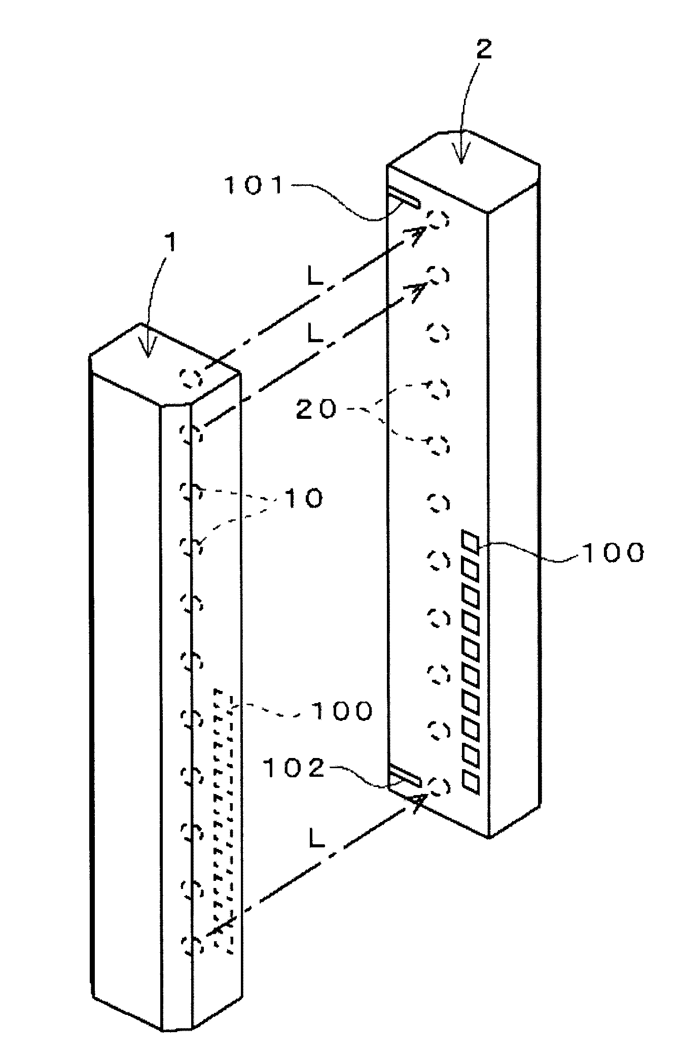
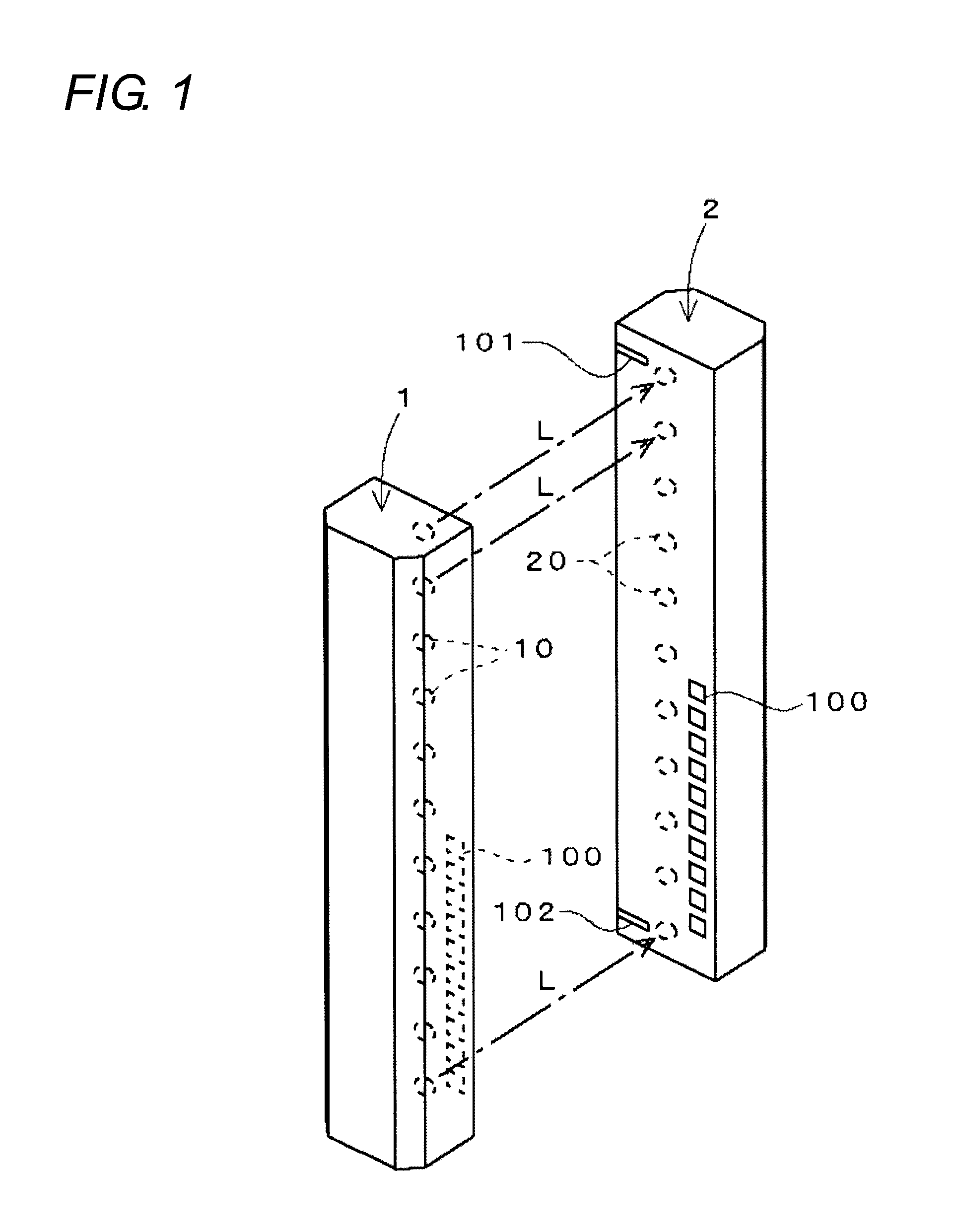
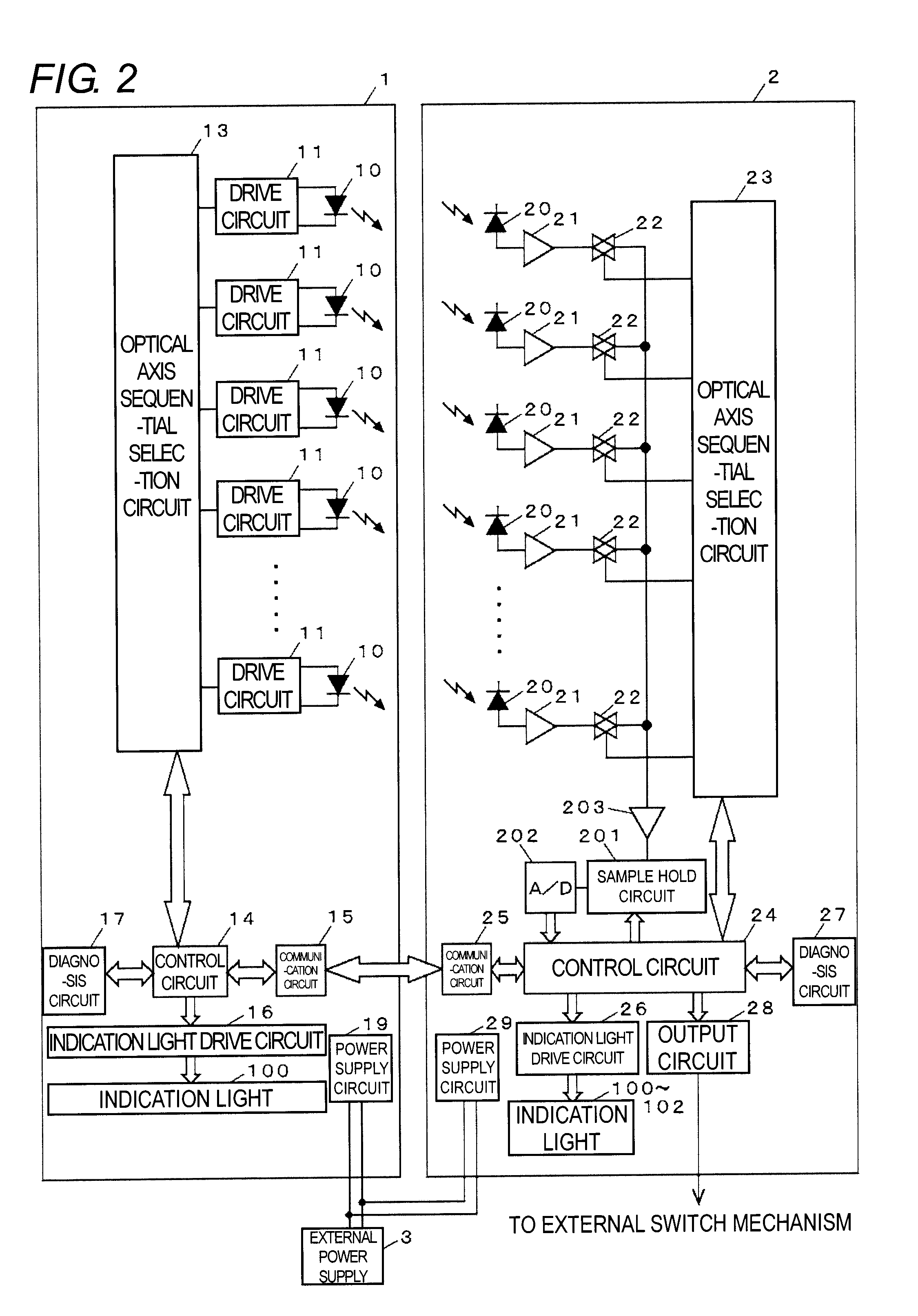
[0042]FIG. 1 shows an outer appearance of a multi-optical axis photoelectronic sensor applied with the present invention. The multi-optical axis photoelectronic sensor is configured by a light projector 1 and a light receiver 2, which have long shapes. A plurality of light emitting elements 10 (LED) is arranged in a line along a longitudinal direction in the light projector 1, and a light receiving element 20 (photodiode) of the same number as the light emitting element 10 is arranged in a line along a longitudinal direction at the same pitch as the light emitting element 10 in the light receiver 2.

[0043]A transparent window (not shown) is respectively formed in a range corresponding to the arrangement of the light emitting elements 10 and the light receiving elements 20 at the front surfaces of the light projector 1 and the light receiver 2. A plurality of (ten in the illustrated example) square indication lights 100 is arranged in a line along the longitudinal direction at the sid...


PUM


Abstract

This invention enables a worker, who performs a work for optical axis adjustment, to easily grasp whether adjustment for further increasing the light receiving quantity is possible. In a multi-optical axis photoelectronic sensor, a minimum value of the light receiving quantities obtained for every optical axis is detected every time a process of measuring, while lighting each light emitting element 10 by turns, the light receiving quantity of a light receiving element corresponding to a lighted light emitting element 10 is repeated for one cycle, and a peak value of the minimum light receiving quantities detected in the past is detected. A bar graph based on specific values of the most recent minimum light receiving quantity and the peak value, or a bar graph showing a proportion of the most recent minimum light receiving quantity with respect to the peak value is displayed using a plurality of indication lights 100, each arranged on the front surfaces of a light projector 1 and a light receiver 2. The bar graph changes according to the update of the peak value and the fluctuation in the value of the minimum light receiving quantity of every hour.

Description

[0001]This nonprovisional application claims priority under 35 U.S.C. §119(a) on Patent Application No. 2008-324077 filed in Japan on Dec. 19, 2008, the entire contents of which are hereby incorporated by reference.BACKGROUND OF THE INVENTION[0002]1. Technical Field[0003]The present invention relates to a multi-optical axis photoelectronic sensor for determining light entering / light shielding state for every plurality of optical axes, and in particular, to a multi-optical axis photoelectronic sensor having a function of outputting information for checking the accuracy of the optical axes alignment between a light projector and a light receiver.[0004]2. Related Art[0005]The light projector and the light receiver of the multi-optical axis photoelectronic sensor have a configuration in which a plurality of light emitting elements or light receiving elements is arranged in a line along a longitudinal direction within a long case body, and are arranged facing each other with the position...

Claims


Application Information

Patent Timeline
Patent Type & Authority Applications(United States)
IPC IPC(8): G01J1/18G01J1/44
CPCG01V8/20
Inventor OSAKO, KAZUNORITAKAHARA, TAKAYOSHI
Owner ORMON CORP
Why Eureka
Try Eureka