Lancing device with trigger mechanism for penetration depth control

a technology of penetration depth control and trigger mechanism, which is applied in the field of lancing devices, can solve the problems of not deep enough, not enough, or at all, and the penetration depth of the lancing device can be too deep in some circumstances

Inactive Publication Date: 2005-05-05
LIFESCAN INC
View PDF18 Cites 128 Cited by
  • Summary
  • Abstract
  • Description
  • Claims
  • Application Information

AI Technical Summary

Benefits of technology

[0008] Lancing devices and associated methods according to embodiments of the present invention provide for a controlled and consistent penetration depth. A lancing device according to an exemplary embodiment of the present invention includes a housing, a lancing mechanism operatively attached to the housing, a pressure tip (e.g., a pressure ring) and a trigger mechanism. The pressure tip is moveably attached to the housing and is configured to engage a target site and create a target site bulge.

Problems solved by technology

Thus, a lancet can potentially penetrate too deeply in some circumstances and not deeply enough, or at all, in other circumstances.

Method used


Image

  • Lancing device with trigger mechanism for penetration depth control
  • Lancing device with trigger mechanism for penetration depth control
  • Lancing device with trigger mechanism for penetration depth control

Examples


Embodiment Construction

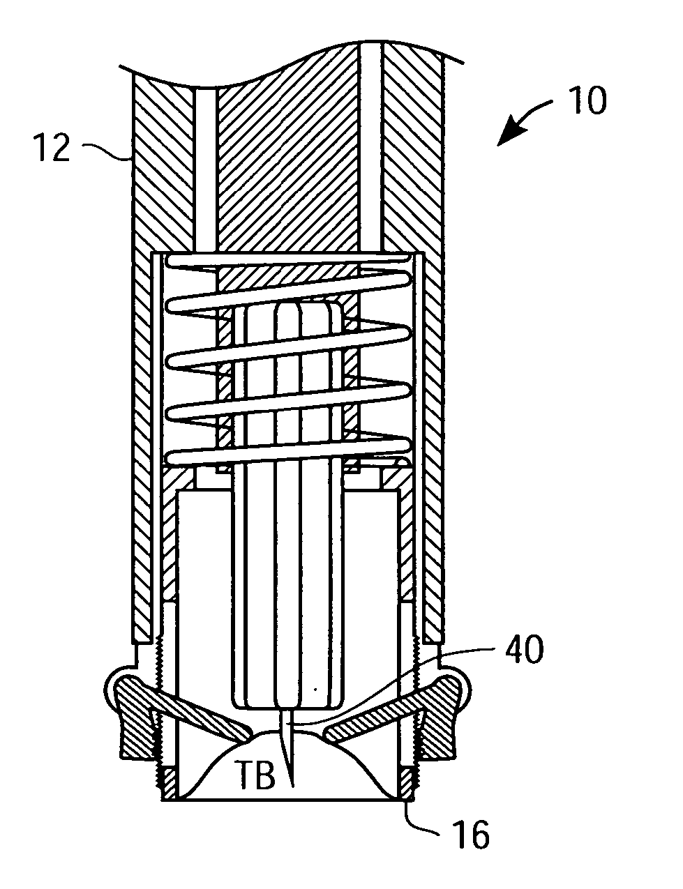
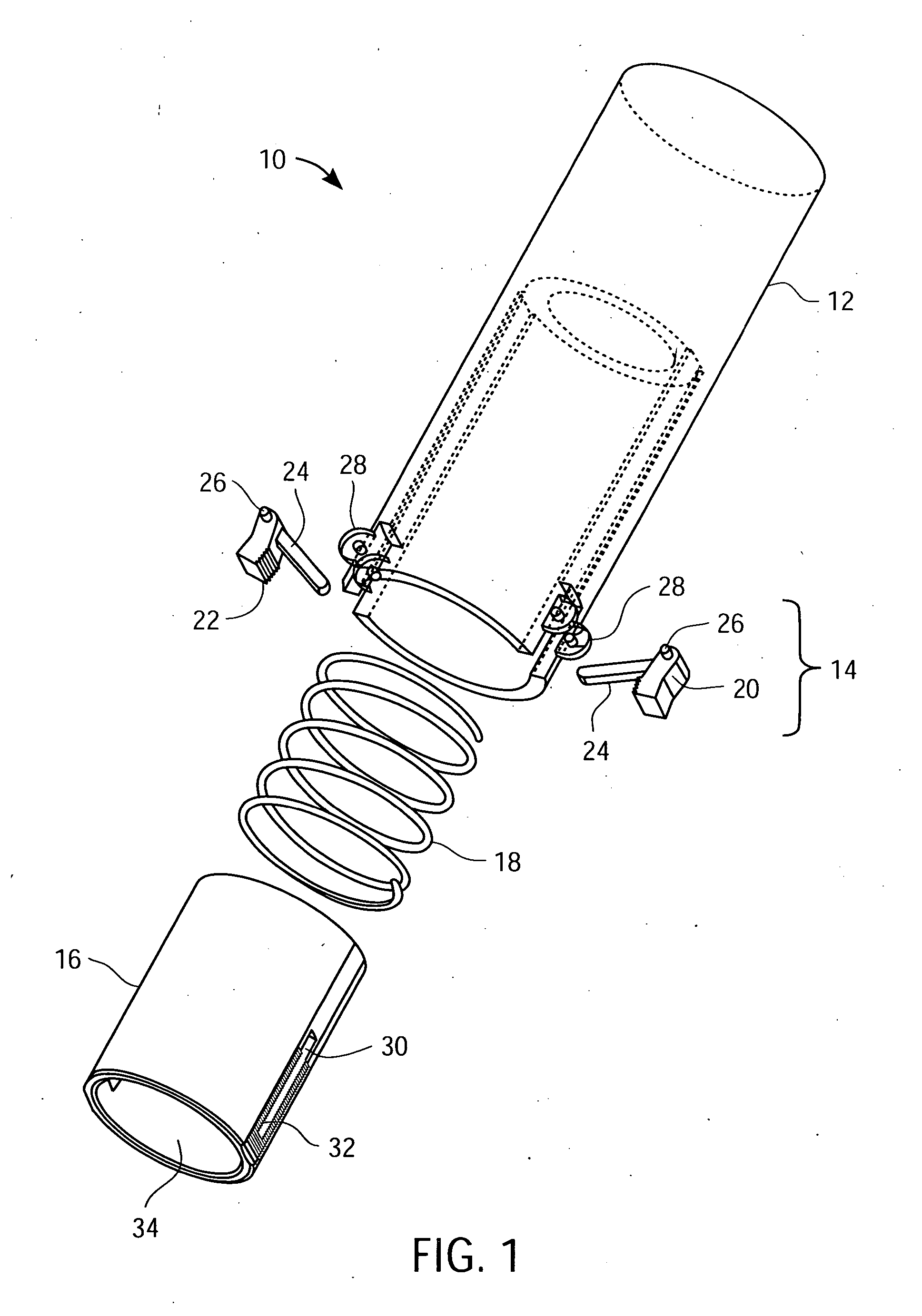
[0020]FIG. 1 shows a perspective exploded view of an exemplary embodiment of a lancing device 10 according to the present invention. Lancing device 10 includes a housing 12, trigger mechanism 14, pressure tip 16, bias spring 18 and a suitable lancing mechanism (not shown). The lancing mechanism is operatively attached to the housing and can include a launch spring, lancet carriage, lancet holder and lancet. Once apprised of the present disclosure, one of ordinary skill in the art will recognize suitable lancing mechanisms. Exemplary lancing mechanisms that are suitable for use are described in U.S. Pat. Nos. 6,045,567 and 6,197,040, each of which is fully incorporated herein by reference.

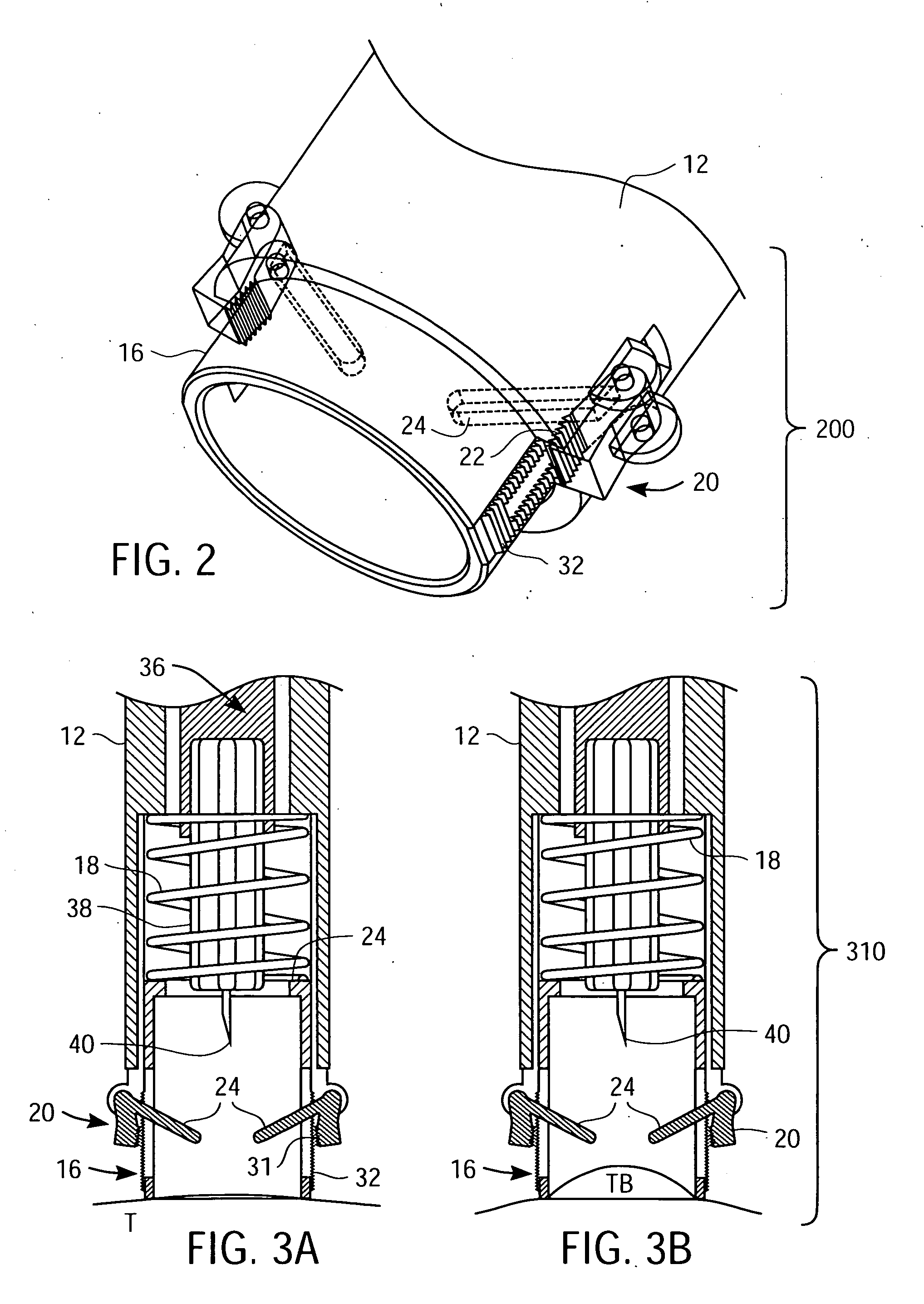
[0021] Trigger mechanism 14 includes two locking pawls 20 (with pawl ratchet teeth 22), pawl trigger arms 24 and axes 26. Trigger mechanism 14 is configured for detecting a target site bulge of a predetermined height and, thereafter, triggering an immobilization (locking) of pressure tip 16 with re...


PUM


Abstract

A lancing device includes a housing, a lancing mechanism operatively attached to the housing, a pressure tip and a trigger mechanism. The pressure tip is moveably attached to the housing and is configured to engage a target site and create a target site bulge. The trigger mechanism is configured for detecting a target site bulge of a predetermined height and, thereafter, triggering an immobilization of the pressure tip with respect to the housing. The immobilization of the pressure tip prevents further change in the location of the target site bulge relative to the housing. Since the location of target site bulge relative to the housing is controlled by the trigger mechanism, via immobilization of the pressure tip, penetration depth is consistent. A method for lancing a target site includes providing the lancing device described above and contacting a pressure tip of the lancing device with the target site. Next, the pressure tip is urged towards the target site, thereby creating target site bulge that is detected by a trigger mechanism of the lancing device. Subsequently, an immobilization of the pressure tip with respect to a housing of the lancing device is triggered. Thereafter, the target site bulge is lanced with a lancet mechanism of the lancing device.

Description

BACKGROUND OF THE INVENTION [0001] 1. Field of the Invention [0002] The present invention relates, in general, to lancing devices and, in particular, to lancing devices with penetration depth control and associated methods of use. [0003] 2. Description of the Related Art [0004] Conventional lancing devices generally have a rigid housing and a lancet that can be armed and launched so as to briefly protrude from one end of the lancing device. For example, conventional lancing devices can include a lancet that is mounted within a rigid housing such that the lancet is movable relative to the rigid housing along a longitudinal axis thereof. Typically, the lancet is spring loaded and launched, upon release of the spring, to penetrate (i.e., “lance”) a target site (e.g., a dermal tissue target site). A biological fluid sample (e.g., a whole blood sample) can then be expressed from the penetrated target site for collection and analysis. Conventional lancing devices are described in U.S. Pat...

Claims


Application Information

Patent Timeline
Patent Type & Authority Applications(United States)
IPC IPC(8): A61B5/15A61B5/151
CPCA61B5/1411A61B5/150022A61B5/150183A61B5/150412A61B5/15107A61B5/15117A61B5/1519A61B5/15194A61B5/1405
Inventor ALLEN, JOHN J.
Owner LIFESCAN INC
Why Eureka
Try Eureka