Face condition determining device and imaging device

Inactive Publication Date: 2008-07-10
PANASONIC CORP
View PDF14 Cites 39 Cited by
  • Summary
  • Abstract
  • Description
  • Claims
  • Application Information

AI Technical Summary

Benefits of technology

[0008]Therefore, a main object of the present invention is to i

Problems solved by technology

When the vehicle is actually driven, however, the position and angle of the driver's face changes because he/she, in one posit

Method used


Image

  • Face condition determining device and imaging device
  • Face condition determining device and imaging device
  • Face condition determining device and imaging device

Examples


embodiment 1

Preferred Embodiment 1

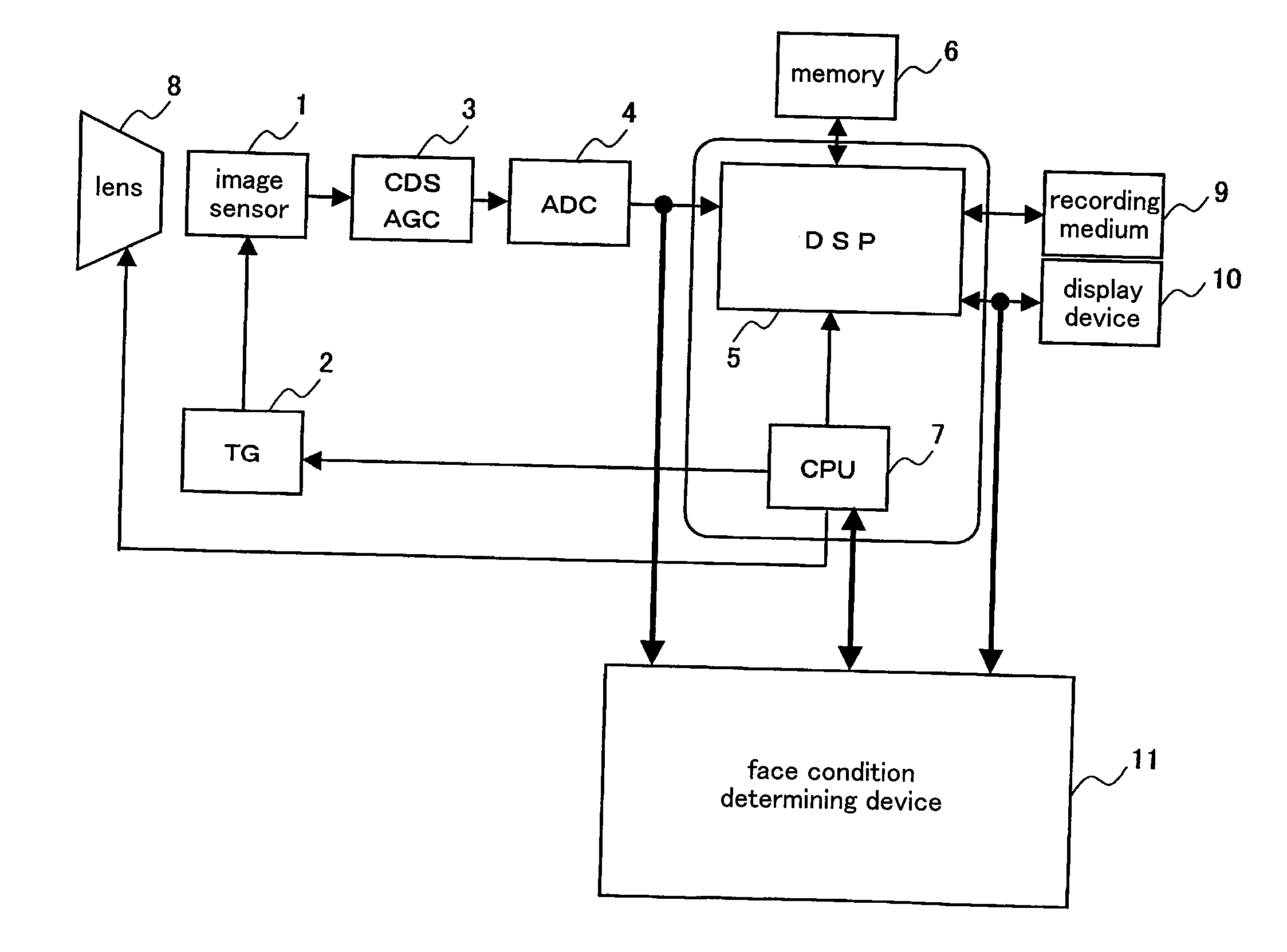
[0039]FIG. 1 is a block diagram illustrating a constitution of an image processing device (camera system) including a face condition determining device according to a preferred embodiment 1 of the present invention. Referring to reference numerals shown in FIG. 1, 1 denotes a two-dimensional image sensor, 2 denotes a timing generator (TG) for generating a drive pulse of the two-dimensional image sensor 1, 3 denotes a CDS / AGC circuit for removing noise of an imaging video signal outputted from the two-dimensional image sensor 1 and controlling a gain thereof, 4 denotes an AD converter (ADC) for converting an analog video signal into digital image data, 5 denotes a DSP (digital signal processing circuit) for executing various types of processing by executing a predetermined program, 6 denotes a memory in which image data and other various types of data are stored, 7 denotes a CPU (microcomputer) for controlling an operation of the entire camera system through a c...

embodiment 2

Preferred Embodiment 2

[0056]A face condition determining device according to a preferred embodiment 2 of the present invention is described in detail referring to the drawings. FIG. 5 is a block diagram illustrating a constitution of the face condition determining device according to the present preferred embodiment. FIG. 6 is a block diagram illustrating a constitution of an imaging device according to the present preferred embodiment. First, the imaging device is described referring to FIG. 6. Referring to reference numerals shown in FIG. 6, 51 denotes a lens unit including an imaging lens, 52 denotes a two-dimensional image sensor, 53 denotes a timing generator (TG) for generating a drive pulse of the image sensor 52, 54 denotes a CDS / AGC circuit for removing noise of an imaging video signal outputted from the image sensor 52 and controlling a gain thereof, 55 denotes an AD converter (ADC) for converting an analog video signal into digital image data, 56 denotes a DSP (digital si...


PUM


Abstract

A face area detector detects a face area of a photographic subject in image data. A particular section detector detects a particular section in the face area. A motion detector extracts a difference between the image data of the particular section in a current frame of the image data and the image data of the particular section in the previous frame of the image data. A face condition determiner determines a face condition of the photographic subject based on the motion information of the particular section.

Description

BACKGROUND OF THE INVENTION[0001]1. Field of the Invention[0002]The present invention relates to a face condition determining device and an imaging device for monitoring and imaging a vehicle driver using an in-vehicle camera and determining if the driver is, for example, drowsy while driving as a part of a fail-safe image processing technology for preventing the occurrence of an accident.[0003]2. Description of the Related Art[0004]In recent years, a camera technology for monitoring a vehicle driver in order to prevent the occurrence of an accident has been increasingly materialized, to which improvement in the speed and image quality of a digital camera has been contributing.[0005]An example of an image processing device for detecting eye conditions of the driver and the like is recited in No. H04-174309 of the Japanese Patent Applications Laid-Open, a basic structure of which is shown in FIG. 8. Referring to reference numerals shown in FIG. 8, 31 denotes an infrared stroboscope f...

Claims


Application Information

Patent Timeline
IPC IPC(8): G06K9/00G06K9/36G06K9/46G06K9/68
CPCG06K9/00221G06V40/16
Inventor HATANO, TOSHINOBU
Owner PANASONIC CORP
Why Eureka
Try Eureka