
Numerical control apparatus for machine tool and numerical control method for machine tool

Inactive Publication Date: 2005-07-21
STAR MICRONICS
View PDF6 Cites 4 Cited by
  • Summary
  • Abstract
  • Description
  • Claims
  • Application Information

AI Technical Summary

Benefits of technology

[0015] Under such circumstances, an object of the invention is to provide a numerical control apparatus for machine tool and a numerical control method for machine tool, in which, when an NC program is transformed into an electronic cam program, a phenomenon for making transformation impossible because of the presence of block skip can be eliminated as much as possible to thereby improve efficiency in transformation of the NC program into the electronic cam program and accordingly improve machining efficiency.
[0029] On this occasion, it is conceived that the coordinate comparison means may perform comparison between the coordinates on the basis of selected tool numbers to thereby easily judge whether the coordinates in the block skip command are the same as the coordinates in the block skip end command.
[0030] It is also conceived that a block skip erasing means is provided for performing a process of erasing erasable block skip end commands and erasable block skip commands at the time of transformation of the NC program into the electronic cam program when a plurality of block skip command-block skip end command combinations are present in the NC program. In this configuration, efficiency in transformation into the electronic cam program can be improved.
[0031] Further, there may be provided: a transformation judgment means for searching for “good” coordinates after the block skip end command when “no good” is decided as a result of comparison by the coordinate comparison means, and performing a judgment, when identical coordinates are detected, as to whether the NC program written in blocks between a block of the detected coordinates and the block skip end command can be transformed into an electronic cam program or not; and a moving means for moving the block skip end command to the rear of a line on which the coordinates are detected when “good” is obtained as a result of the judgment by the transformation judgment means. In this configuration, efficiency in transformation into the electronic cam program can be improved.
[0032] Further, there may be provided: a transformation judgment means for searching for “good” coordinates after the block skip end command when “no good” is decided as a result of comparison by the coordinate comparison means, and performing a judgment, when identical coordinates are detected, as to whether the NC program written in blocks between a block of the detected coordinates and the block skip end command can be transformed into an electronic cam program or not; a movement judgment means for performing a judgment, when “no good” is given as a result of the judgment by the transformation judgment means, as to whether a command causing “no good” of transformation can be moved to the rear of the block of the detected coordinates without any trouble; and a “no good” causal command moving means for moving the command causing “no good” of transformation to a line on the rear of the block of the detected coordinates when “good” is given as a result of the judgment by the movement judgment means. In this configuration, efficiency in transformation into the electronic cam program can be improved.
[0033] Further, there may be provided: an NC program storage portion for storing an NC program generated for machining a material into a desired shape; a block skip command detection means for detecting whether a block skip command for skipping execution of blocks after a position where the block skip command is described is present in the NC program stored in the NC program storage portion or not; a block skip end command detection means for detecting whether a block skip end command provided in connection with the block skip command to permit execution of blocks after a position where the block skip end command is described is present in the NC program stored in the NC program storage portion or not; a block skip erasure judgment means for judging whether both the block skip command and the block skip end command detected by the block skip command detection means and the block skip end command detection means respectively can be erased or not; a block skip erasure means for erasing the block skip command and the block skip end command when the block skip erasure judgment means makes a decision that these commands can be detected; and a program transformation means for transforming the NC program into an electronic cam program. In this configuration, the possibility of transformation into the electronic cam program can be improved because transformation into the electronic cam program is executed in the condition that erasable block skip processes are erased to reduce the number of block skip processes.

Problems solved by technology

On the other hand, when the machine tool is to be operated under electronic cam program control, it is difficult to change data in accordance with whether block skip is executed or not, because the electronic cam program for operating the machine tool is a fixed program.
Moreover, if block skip is executed, there is a high possibility that continues data cannot be obtained.
Accordingly, when continuous data as described above are not obtained, there is fear that position control cannot be made.
In this case, the locus of the NC program before transformation is however changed, so that the possibility of interference of the machine tool increases undesirably.
In addition, there is an undesirable possibility that the machine tool cannot operate in accordance with the locus intended by the user.
Accordingly, there are a lot of NC programs that cannot be transformed into electronic cam programs.
As a result, there is a problem that an effect of improving machining efficiency cannot be obtained sufficiently.

Method used


Image

  • Numerical control apparatus for machine tool and numerical control method for machine tool
  • Numerical control apparatus for machine tool and numerical control method for machine tool
  • Numerical control apparatus for machine tool and numerical control method for machine tool

Examples


Embodiment Construction

[0043] An embodiment of the invention will be described below with reference to FIGS. 1 to 7.

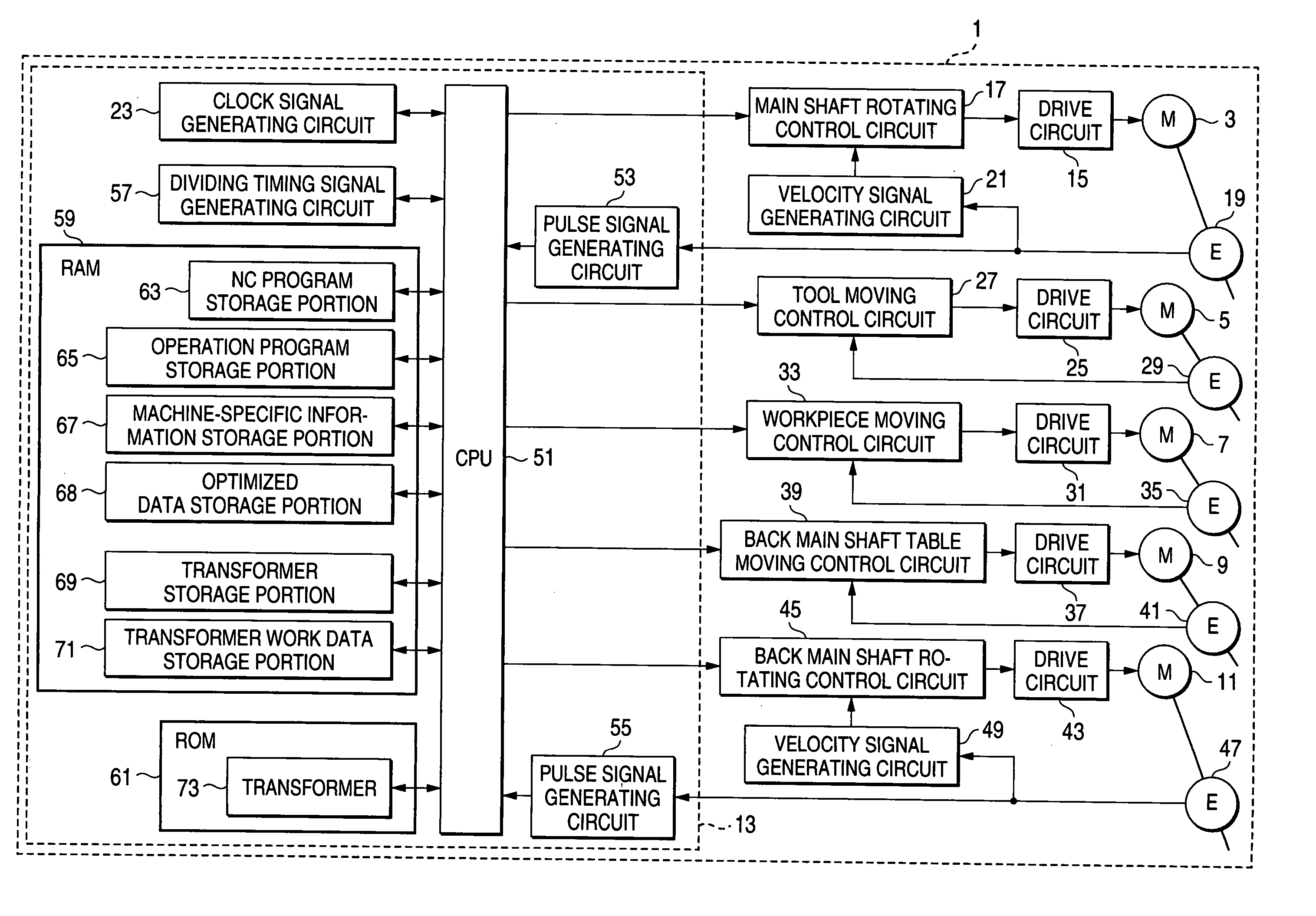
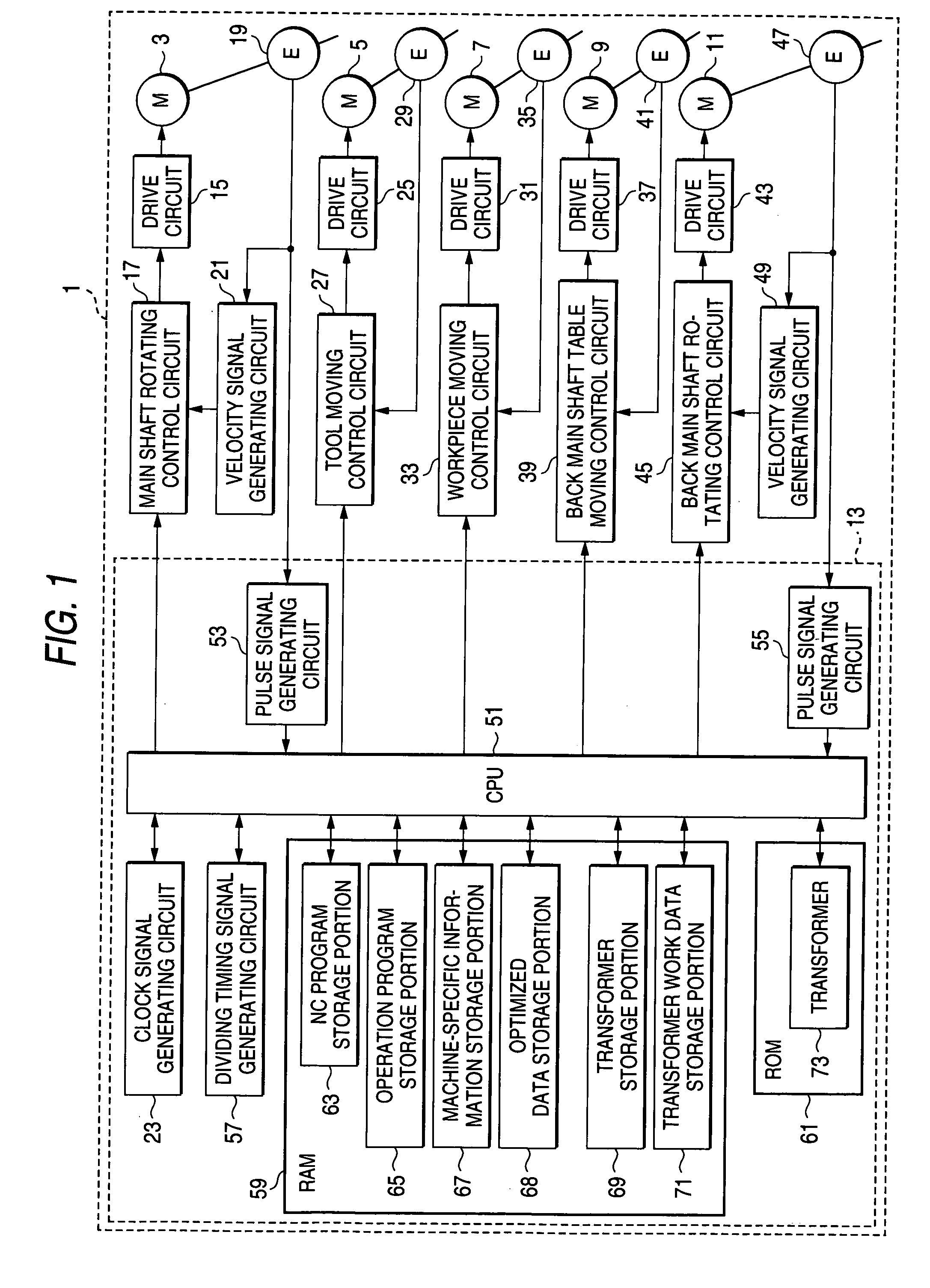
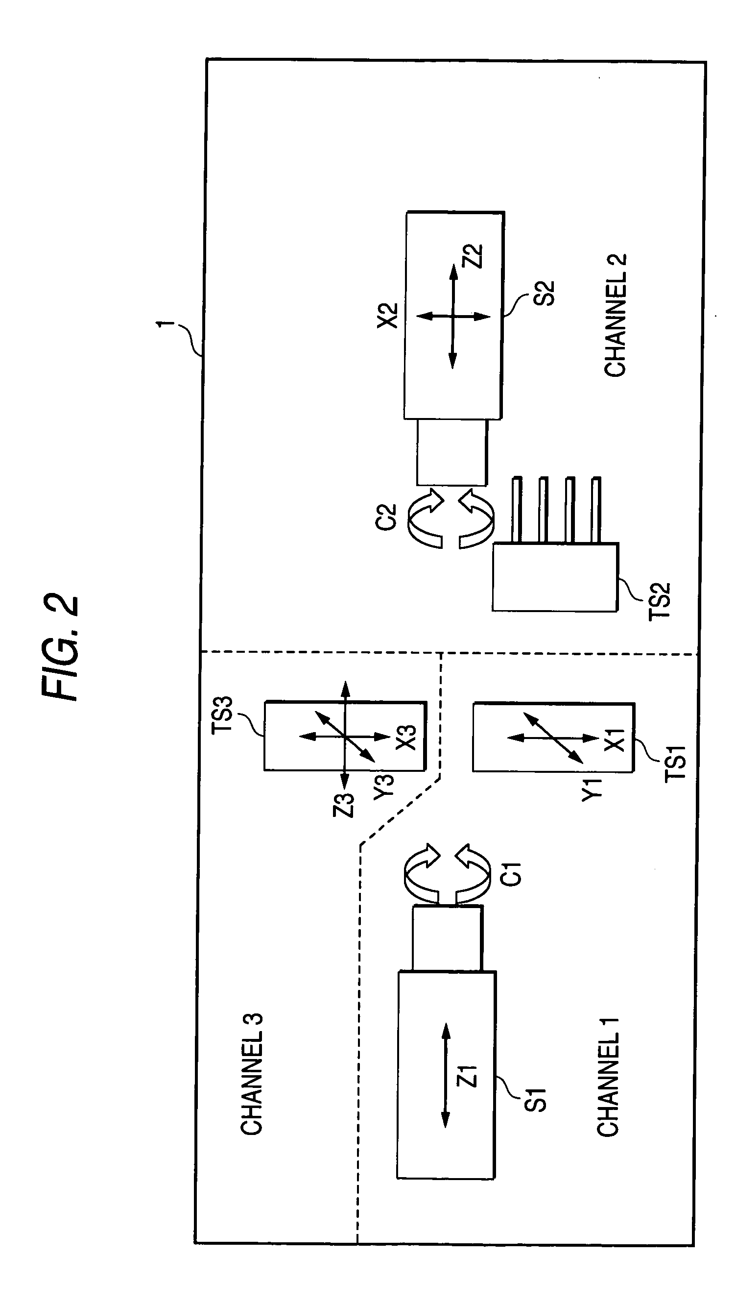
[0044]FIG. 1 is a block diagram showing the overall configuration of a numerical control machine tool according to this embodiment. FIG. 2 is a plan view showing the schematic control axis configuration of the numerical control machine tool.

[0045] In FIG. 1, the numerical control machine tool 1 includes a main shaft rotating motor 3, a tool moving motor 5, a workpiece moving motor 7, a back main shaft moving motor 9, a back main shaft rotating motor 11, and a control unit portion 13 for controlling drives of the main shaft rotating motor 3, the tool moving motor 5, the workpiece moving motor 7, the back main shaft moving motor 9 and the back main shaft rotating motor 11.

[0046] The main shaft rotating motor 3 is provided so that a main shaft (designated by the symbol S1 in FIG. 2) formed so as to be able to hold a workpiece is driven to rotate. The main shaft rotating motor 3 is connected ...


PUM


Abstract

A numerical control apparatus for machine tool, includes: an NC program storage portion for storing an NC program; a block skip command detection portion for detecting whether a block skip command for skipping execution of blocks after a position where the block skip command is described is present in the NC program stored in the NC program storage portion or not; a block skip end command detection portion for detecting whether a block skip end command provided in connection with the block skip command to permit execution of blocks after a position where the block skip end command is described is present in the NC program or not; and a coordinate comparison portion for performing comparison concerning a difference between coordinates on at least one control axis in the block skip command and the block skip end command.

Description

BACKGROUND OF THE INVENTION [0001] 1. Field of the Invention [0002] The present invention relates to a numerical control apparatus for machine tool and a numerical control method for machine tool. Particularly it relates to a numerical control apparatus and method in which efficiency in transformation of an NC program into an electronic cam program can be improved to thereby attain improvement in machining efficiency. [0003] 2. Background Art [0004] There is commonly known a numerical control machine tool used for machining a material into a desired shape by using a tool such as a cutter in the condition that the material is set in the machine tool. For example, the numerical control machine tool operates as follows. A numerical control program (NC program) is generated. Respective portions inclusive of the tool such as a cutter are operated automatically by the NC program to thereby obtain a product processed into a desired shape. [0005] The NC program per se generated for obtainin...

Claims


Application Information

Patent Timeline
IPC IPC(8): B23Q15/00G05B19/408G05B19/4093G05B19/414
CPCG05B19/408G05B2219/36045G05B2219/34343
Inventor SUGIYAMA, TETSUYA
Owner STAR MICRONICS
Learn More