Image forming apparatus and foam application device

a technology of foam application and forming apparatus, which is applied in the direction of electrographic process apparatus, printing, instruments, etc., can solve the problems of irregular application of pretreatment liquid, large power consumption of the apparatus, and time-consuming drying of liquid droplets ejected on the sh

Inactive Publication Date: 2011-03-10
RICOH KK
View PDF11 Cites 31 Cited by
  • Summary
  • Abstract
  • Description
  • Claims
  • Application Information

AI Technical Summary

Benefits of technology

[0011]The present invention has been made in light of the above problems and may have an object of applying a foamed liquid or a gel or both the foamed liquid and the gel with an even thickness. Also, the present invention may have an object of preventing the application of the foam to an unnecessary part when the liquid or the gel is or both the liquid and the gel are foamed with air.

Problems solved by technology

Therefore, there arises problems such as “feathering” in which dots formed by the liquid droplets are disordered in the shape of whiskers and “color bleed” in which different colors of ink droplets are mixed together to make a color border unclear when they are adjacently ejected on a sheet.
In addition, it takes time to dry the liquid droplets ejected on the sheet.
However, when the heating unit is provided as described in Patent Document 1, the power consumption of an apparatus becomes large.
Furthermore, when the pretreatment liquid is applied with the application roller and the liquid ejection head as described in Patent Documents 2 and 3, irregularities in the application of the pretreatment liquid are caused.
In addition, since the liquid is excessively applied onto the sheet, the quick-drying property of the sheet after reacting with the ink is degraded.
Particularly, the sheet is likely to be curled and deflected, which results in occurrence of jamming, etc.

Method used


Image

  • Image forming apparatus and foam application device
  • Image forming apparatus and foam application device
  • Image forming apparatus and foam application device

Examples


first embodiment

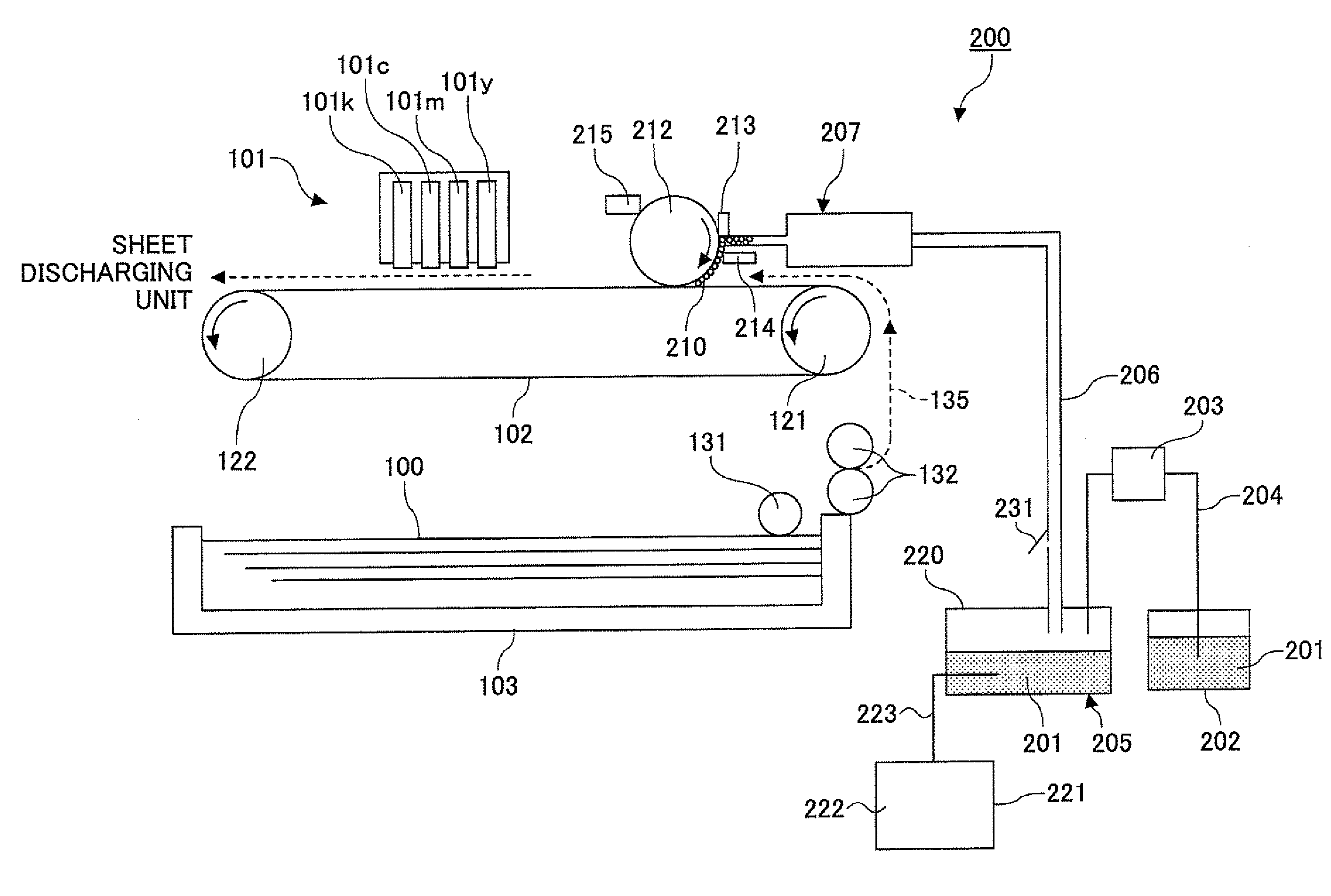
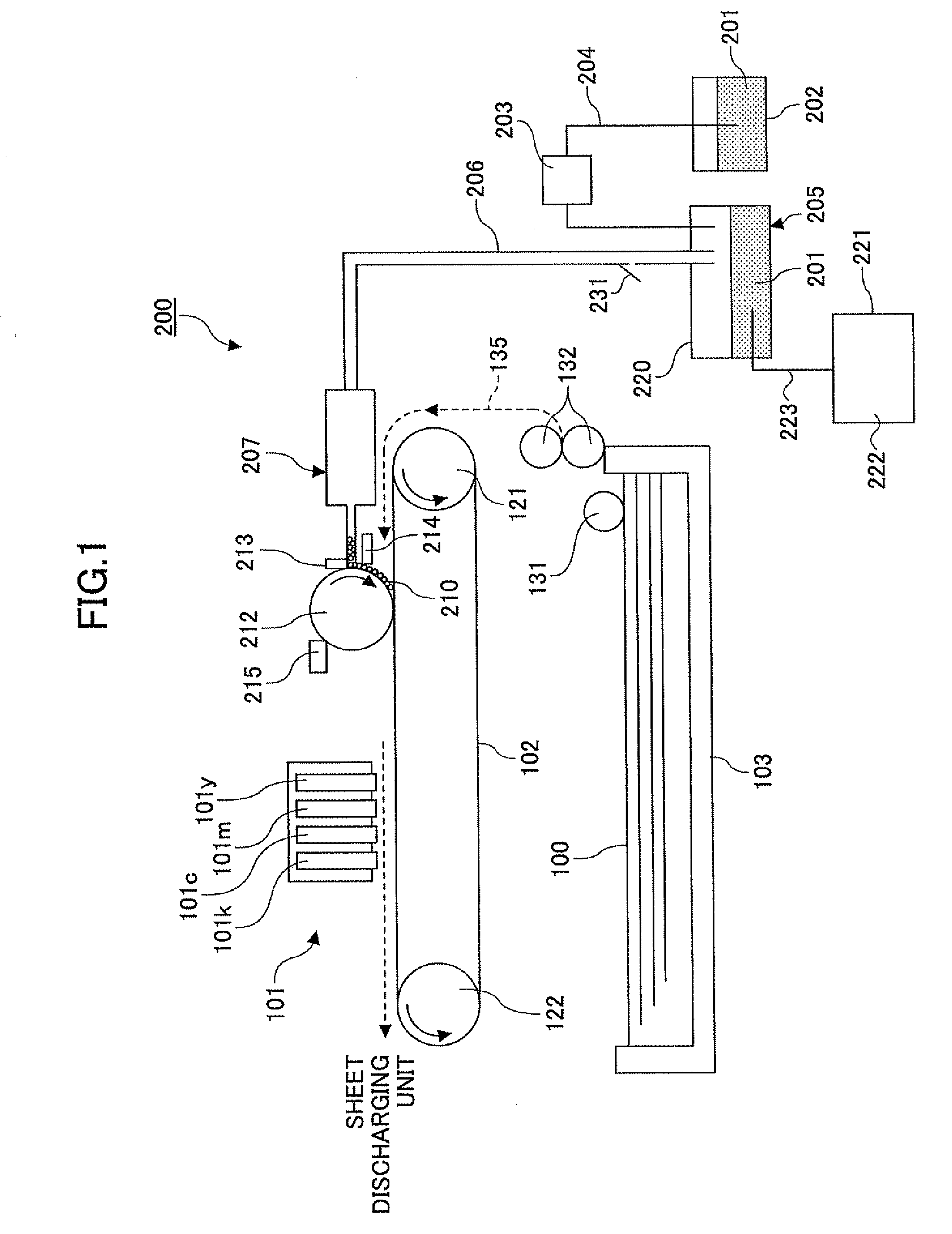
[0030]Referring to the accompanying drawings, a description is now made of the embodiments of the present invention. First, an example of an image forming apparatus having a foam application device according to the present invention is described based on FIG. 1. Note that FIG. 1 is the entire configuration diagram of the image forming apparatus.

[0031]The image forming apparatus has a recording head unit 101 as an image forming unit that ejects liquid droplets to a sheet 100 as a medium to be recorded to form an image; a conveyance belt 102 that conveys the sheet 100; a sheet feeding tray 103 that accommodates the sheet 100; and a foam application device 200 (device that applies foam to a member to be applied) according to the embodiments of the present invention that applies foam to the sheet 100 as the member to be applied on the upstream side of the recording head unit 101 in a sheet conveyance direction.

[0032]The recording head unit 101 is composed of a line-type liquid ejection ...

second embodiment

[0063]Next, referring to a schematic diagram shown in FIG. 4, the foam application device according to the present invention is described.

[0064]In this embodiment, one or more foam shear members 225 (i.e., two foam shear members 225a and 225b) that micronize the foam are provided in the foam supplying path 206. When desired fine foam 210 suitable for image formation cannot be obtained only with the shear member 224 provided at the tip end of the high-pressure air feeding unit in the foam generation unit 205, the foam 210 (called “large foam”) generated by the foam generation unit 205 is sheared with the foam shear member 225a of the foam supplying path 206 to be micronized into medium foam 210b, and then it is further sheared with the foam shear member 225b to be micronized into small foam 210.

[0065]With this configuration, the foam application device can efficiently generate the foam 210 suitable for application and supply it to the foam supplying unit 207.

[0066]Note that in this c...

third embodiment

[0073]Then, referring to a schematic diagram shown in FIG. 5, the foam application device according to the present invention is described.

[0074]In this embodiment, the foam application device is provided with an outflowing agent receiving unit 232 that collects the foam 210 outflowing from the foam supplying path 206 when the opening / closing valve 231 of the foam supplying path 206 is opened and closed, an outflowing agent supplying path 233 through which the foam (or the processing liquid 201 converted from the foam: an outflowing agent) collected into the outflowing agent receiving unit 232 is supplied, an outflowing agent supplying unit 234 such as a pump, and an outflowing agent storage unit 235 that stores the outflowing agent.

[0075]In other words, as described above, when the opening / closing valve 231 is opened, the foam 210 in the foam supplying path 206 is returned in the direction to the foam generation container 220 of the foam generation unit 205. At this time, some foam ...


PUM


Abstract

An image forming apparatus is disclosed that includes an image forming unit that forms an image on a medium to be recorded; and a foam application unit that applies a foam generated from at least any one of a liquid and a gel to the medium to be recorded or an intermediate member for applying the foam to the medium to be recorded. The foam application unit has a foam generation unit that generates the foam, an application unit that applies the generated foam to the medium to be recorded or the intermediate member, a foam supplying path through which the generated foam is supplied to the application unit, and a unit that increases a volume of the foam supplying path. The foam application unit increases the volume of the foam supplying path when stopping the supply of the foam to the application unit.

Description

TECHNICAL FIELD[0001]The present invention relates to an image forming apparatus and a foam application device.BACKGROUND ART[0002]As image forming apparatuses such as printers, facsimile machines, copiers, plotters, and multi-task machines having plural such functions, ink jet recording apparatuses of a liquid ejection recording type using a recording head that ejects, for example, ink liquid droplets are known. The image forming apparatus of this type ejects ink droplets from the recording head onto a sheet (that is not limited to a paper, but it means one such as an overhead transparency film to which ink droplets and other liquids can be attached and referred to be a medium to be recorded, a recording paper, or a recording sheet) during conveyance to perform image formation (used synonymously with recording, printing, and imaging). Examples of the image forming apparatus include a serial-type image forming apparatus in which the recording head ejects liquid droplets to form an i...

Claims


Application Information

Patent Timeline
Patent Type & Authority Applications(United States)
IPC IPC(8): B41J2/015
CPCG03G15/2096B41J11/0015
Inventor IZUMIKAWA, MANABUMATSUMOTO, KAZUYOSHIICHIMURA, MINORIIMOTO, SHINJI
Owner RICOH KK
Why Eureka
Try Eureka