Engagement structure between a mouth member of a pressure vessel and a blow pin, mouth member structure of a pressure vessel having the engagement structure and method of making a pressure vessel

a technology of engagement structure and pressure vessel, which is applied in the direction of vessel construction details, mechanical devices, other domestic objects, etc., can solve the problems of cracks in the bonding interface, the state of bonding between the coating and the blow pin cannot be easily prevented, and the bonding strength reduction

Active Publication Date: 2013-02-28
YACHIYO IND CO LTD
View PDF2 Cites 15 Cited by
  • Summary
  • Abstract
  • Description
  • Claims
  • Application Information

AI Technical Summary

Benefits of technology

[0025]The present invention provides, with respect to a pressure vessel including a plastic liner which is blow molded with a mouth member inserted therein, an engagement structure to be provided between the mouth member of the pressure vessel and a blow pin which prevents any rotational load to be applied to the bonding interface between the mouth member and the plastic liner when removing the blow pin, a mouth member structure of a pressure vessel having such an engagement structure and a method of making such a pressure vessel.
[0026]FIG. 1 is a side view of a pressure vessel embodying the present invention partly in section;
[0027]FIG. 2 is an enlarged sectional view of a part of FIG. 1 indicated by arrow II showing the state of bonding between a plastic liner and a mouth member in the pressure vessel embodying the present invention;
[0028]FIG. 3 is a schematic sectional diagram showing a blow molding process given as an example of a manufacturing process embodying the present invention; and
[0029]FIGS. 4a and 4b are detailed sectional views of a part of FIG. 3 indicated by arrow IV showing the state of engagement between the mouth member and a blow pin in the pressure vessel embodying the present invention.

Problems solved by technology

The technology disclosed in Patent Document 3 consists of forming a plastic liner by blow molding with a mouth member inserted thereof, and this does not easily allow the state of bonding between the coating on the surface of the mouth member and the plastic liner to be verified upon completion of the molding process.
According to such a structure, when removing the blow pin upon completion of the molding process, the rotational load that is applied to the mouth member adversely affects the state of bonding between the mouth member and the plastic liner so that the reduction in the bonding strength and the creation of cracks in the bonding interface could not be easily prevented.

Method used


Image

  • Engagement structure between a mouth member of a pressure vessel and a blow pin, mouth member structure of a pressure vessel having the engagement structure and method of making a pressure vessel
  • Engagement structure between a mouth member of a pressure vessel and a blow pin, mouth member structure of a pressure vessel having the engagement structure and method of making a pressure vessel
  • Engagement structure between a mouth member of a pressure vessel and a blow pin, mouth member structure of a pressure vessel having the engagement structure and method of making a pressure vessel

Examples


Embodiment Construction

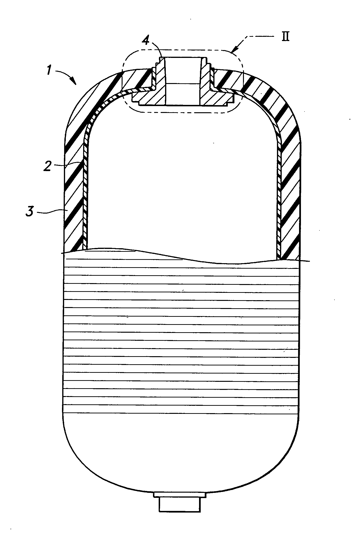
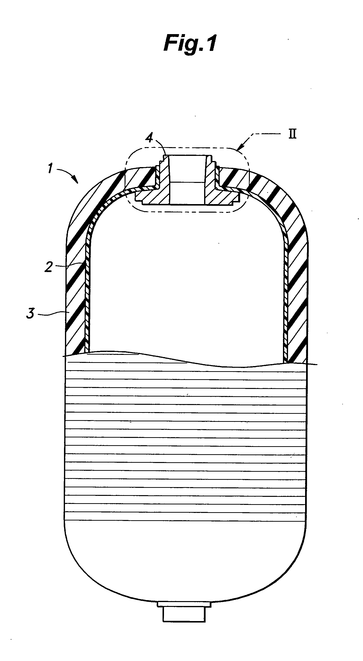
[0030]An example of a pressure vessel 1 to which the present invention is applied is described, and, then, an engagement structure between a mouth member 4 of the pressure vessel 1 and a blow pin 11, a mouth member structure of the pressure vessel 1 and a manufacturing method of the pressure vessel are described in the following. Referring to FIG. 1, the pressure vessel 1 comprises a plastic liner 2 for receiving primarily gas or liquid therein, a fiber reinforced plastic layer 3 reinforcing the outer surface of the plastic liner 2 and a mouth member 4 projecting out of the plastic liner 2 and the fiber reinforced plastic layer 3 for introducing and expelling air or gas into and out of the pressure vessel 1. The detailed bonding structure between the plastic liner 2 and the mouth member 4 is omitted in FIG. 1, and will be described in more detail hereinafter.

[0031]The plastic liner 2 constitutes a vessel for receiving gas or liquid, and can be made of material that suits the content...


PUM

PropertyMeasurementUnit
pressureaaaaaaaaaa
pressureaaaaaaaaaa
engagement structureaaaaaaaaaa

Abstract

In a pressure vessel which is formed by blow molding a plastic liner with a mouth member fitted on a blow pin, a rotational torque is prevented from being applied between the mouth member and the blow pin when removing the blow pin. A parison is placed around the mouth member which is fitted on the blow pin, and is blow molded with a die assembly placed around the parison so that a vessel shaped plastic liner is formed. An engagement structure which is provided between the mouth member of the pressure vessel and the blow pin includes a ball moveably received in a radial through hole of the peripheral wall of the blow pin, and a release groove formed on an inner circumferential surface of the mouth member and having a prescribed depth. When the blow pin is introduced into the mouth member until the ball and the release groove oppose each other, the ball moves radially outward and becomes partly received by the release groove to engage the mouth member with the blow pin.

Description

TECHNICAL FIELD[0001]The present invention relates to an engagement structure between a mouth member of a pressure vessel for storing compressed gas such as liquefied petroleum gas (LPG) and a blow pin, and a seal structure for such a pressure vessel.BACKGROUND OF THE INVENTION[0002]LPG contributes to the prevention of acid rain because of a low sulfur content thereof, and the burned gas contains a relatively small amount of CO2 as compared with petroleum and coal. Therefore, LNG is considered as an ecological, clean energy source. LNG can be liquefied under a relatively low pressure, and the liquefied volume thereof is a 250th of the original gas volume. Furthermore, LNG can be stored and transported in a tank which is capable of withstanding a relatively low pressure. Currently, steel pressure vessels are commonly used for storing and transporting LNG in Japan, but light weight pressure vessels made of composite materials based on plastic technology are widely used in western coun...

Claims


Application Information

Patent Timeline
Patent Type & Authority Applications(United States)
IPC IPC(8): F17C1/02F17C1/16B29C49/06
CPCB29C49/04F17C2223/036B29C2049/2008B29C2049/2047B29C2049/2078B29L2031/7172F17C1/06F17C1/16F17C2201/0109F17C2201/056F17C2203/0604F17C2203/0619F17C2203/0636F17C2203/066F17C2203/0665F17C2203/0668F17C2203/067F17C2209/2127F17C2209/227F17C2209/234F17C2221/035B29C49/20F17C2205/0305B29C49/24B29C2049/2404B29C2049/2443
Inventor TANI, TATSUSHIOHASHI, JUNTASHIRO, MASAHIRO
Owner YACHIYO IND CO LTD
Why Eureka
Try Eureka