Spark plug

a technology of spark plugs and spark plugs, which is applied in the manufacture of spark plugs, spark plugs, machines/engines, etc., can solve the problems of increasing the risk of breaking the insulator due to a reduction in strength, difficulty in packing talc or the like into the interior of the crimp portion, and difficulty in reducing the diameter of the insulator, so as to prevent the eccentricity of the insulator and improve the production yield. , the effect of improving

Inactive Publication Date: 2007-02-22
NGK SPARK PLUG CO LTD
View PDF6 Cites 19 Cited by
  • Summary
  • Abstract
  • Description
  • Claims
  • Application Information

AI Technical Summary

Benefits of technology

[0017] A spark plug which can improve the breakage resistance of the insulator and prevent eccentricity of the insulator at the time of assembly can be realized by forming a groove portion on the insulator and forming a glaze layer up to a point between the groove portion and the shoulder portion according to (1) above. By providing a groove portion, it becomes possible to avoid certain production steps otherwise needed for excessively accurate control of application amount and for checking the portion where the glaze layer is formed, to thereby improve production yield. This is because the softened glaze that flows downwards at the time of glaze firing can be accommodated within the groove, whereby application of the glaze to the maximum diameter portion can be avoided without fail. The groove portion preferably has a width (D) of at least 0.3 mm but not greater than 1.0 mm, and also preferably has a depth (C) of at least 50 μtm but not greater than 200 μm as measured from surface of the intermediate diameter portion.
[0018] In the case where the surface of the insulator is exposed at the maximum diameter portion located forward of the groove portion of the insulator as in embodiment (2) above, i.e., when the glaze layer is not formed on the surface of the maximum diameter portion with the groove portion serving as a boundary, problems in assembly and in the insulator becoming eccentric at the time of assembly can be eliminated.
[0019] A spark plug having the above-described structure is preferably fabricated such that the difference in radius between the maximum diameter portion and the intermediate diameter portion is equal to or greater than 0.05 mm but not greater than 0.15 mm as described in (3) above. The intermediate diameter portion accommodates excess glazing material. To accommodate excess glaze material, the intermediate diameter portion preferably has an axial length equal to or greater than 2.0 mm (but not greater than 5.0 mm). When the radius difference is less than 0.05 mm, however, the intermediate diameter portion cannot efficiently accommodate excess glazing material. This is because the outermost portion in the radial direction of the glaze layer formed on the intermediate diameter portion excluding the groove portion may be located on the outer side of the maximum diameter portion. In such a case, when the insulator having the glaze layer formed thereon is assembled to the metallic shell, the axis of the metallic shell and that of the insulator may deviate from each other, or assembly may become difficult. Meanwhile, when the difference in radius exceeds 0.15 mm, the area of engagement between the crimp portion of the metallic shell and the shoulder portion of the insulator decreases, and it becomes difficult to sufficiently maintain air-tightness of the combustion chamber. By setting the difference in radius to a value equal to or greater than 0.05 mm but not greater than 0.15 mm, it becomes possible to form on the insulator a glaze layer having a proper thickness, and to avoid failure during assembly of the metallic shell and the insulator. Notably, the radius difference can be controlled on the basis of dimensions before forming the glaze layer.

Problems solved by technology

However, if the diameter of the entire insulator, which is formed of a fired ceramic, is reduced, the risk of breaking the insulator increases due to a reduction in strength.
Therefore, reducing the diameter of the insulator is not a preferred approach.
However, since the crimp portion comes closer to the rear trunk portion, it becomes difficult to pack talc or the like into the interior of the crimp portion (the clearance between the crimp portion and the rear trunk portion) as in the case of the above-described conventional structure.
If a formed glazed layer has a non-circular cross section, flashover disadvantageously becomes difficult to prevent, and appearance is impaired.

Method used


Image

  • Spark plug
  • Spark plug
  • Spark plug

Examples


example 1

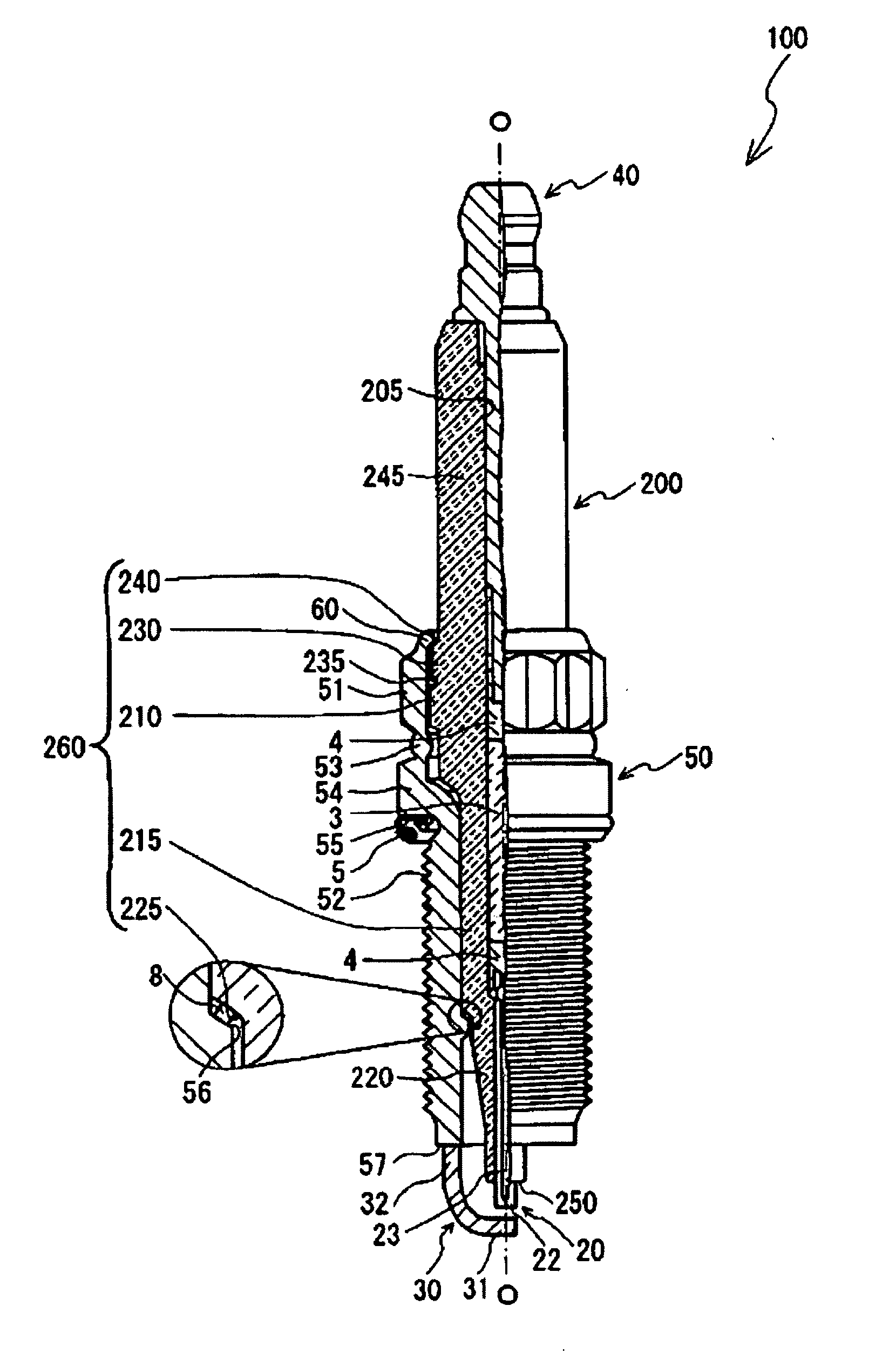
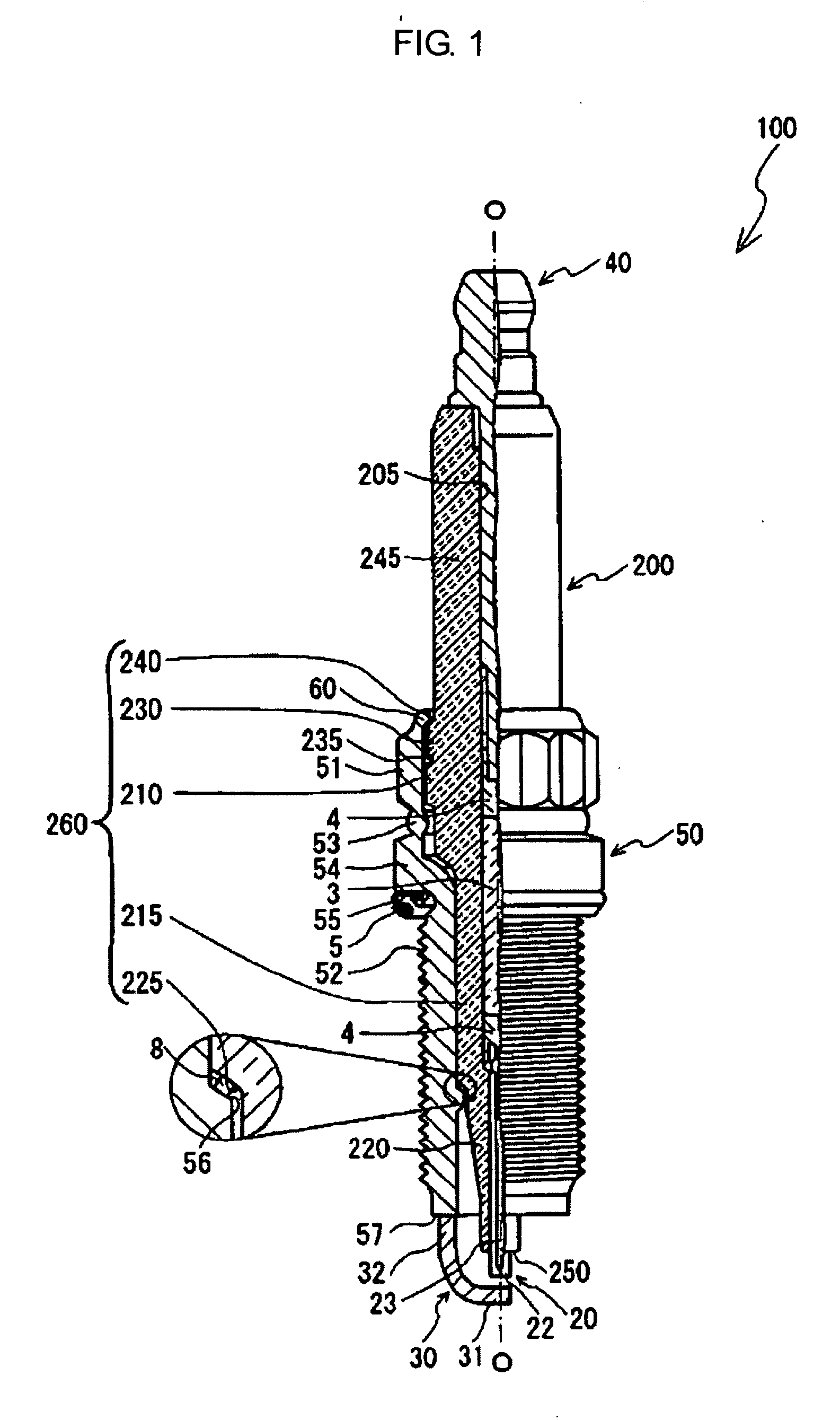
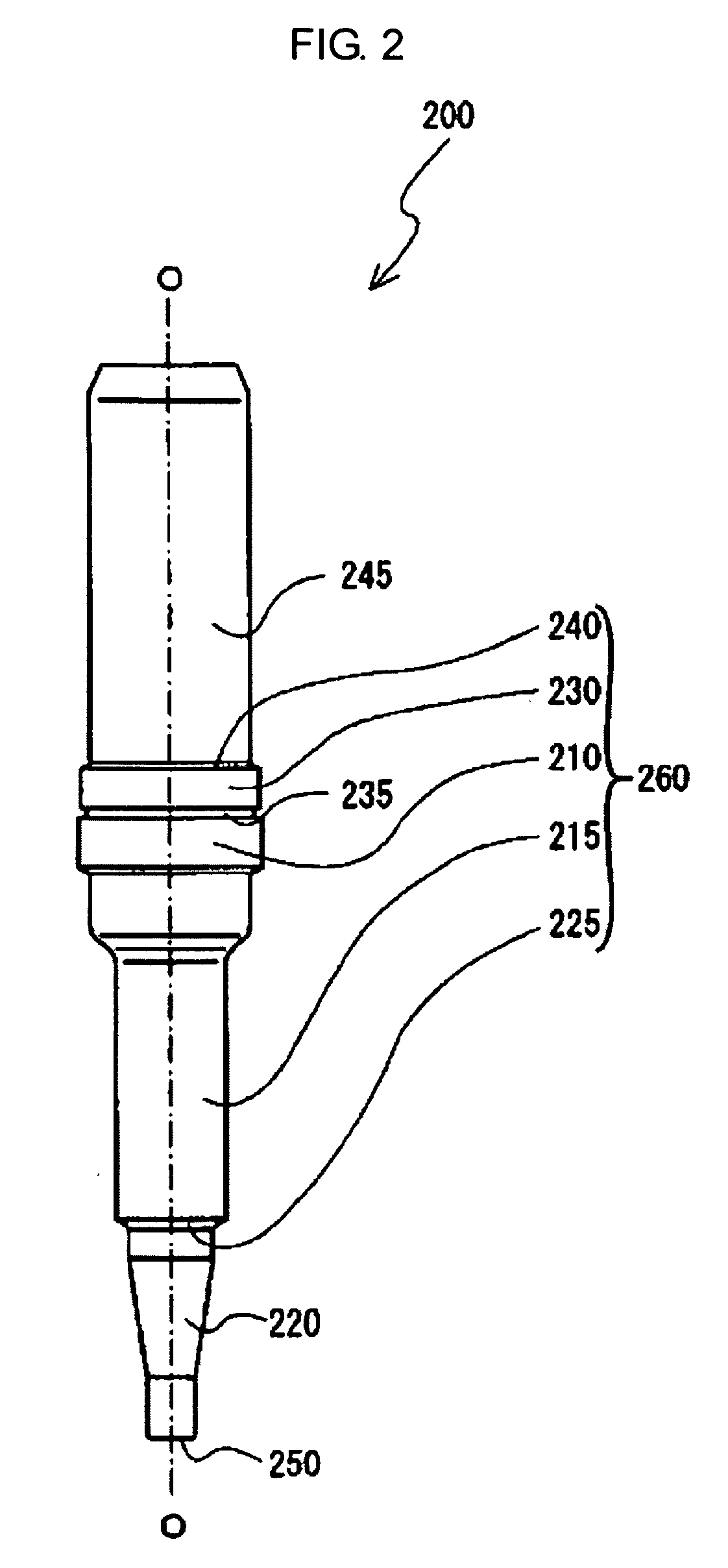
[0051] An evaluation test was performed in order to confirm the effect attained by making the outer diameter B of the maximum diameter portion 210 greater than the outer diameter A of the intermediate diameter portion 230. In this evaluation test, five samples were prepared for each of five types of insulators differing in radius between the outer diameter B of the maximum diameter portion and the outer diameter A of the intermediate diameter portion. The specific method used to prepare the samples is described below.

[0052] Insulators were fabricated such that after firing, the outer diameter A of the intermediate diameter portion and the outer diameter B of the maximum diameter portion had target values of 11.6 mm and 11.8 mm, respectively, and the intermediate diameter portion had a dimensional error of ±0.05 mm. Subsequently, the radius difference (B-A) / 2 of each insulator was measured; and the insulators were sorted by radius difference into five types or groups; i.e., a 0.03 m...


PUM


Abstract

A spark plug in which a glaze is applied to a rear trunk portion (245), a shoulder portion (240), and a portion of a intermediate diameter portion (230) of an insulator (200), and glaze firing is performed. Even when the glaze (shown by dots in the drawings) softened by heating flows downwards, the glaze is accommodated within a groove portion (235) formed between the shoulder portion (240) and the maximum diameter portion (210), and does not reach the maximum diameter portion (210). Such structure facilitates assembly of the insulator (200) to a metallic shell in a spark plug manufacturing process.

Description

BACKGROUND OF THE INVENTION [0001] 1. Field of the Invention [0002] The present invention relates to a spark plug having a metallic shell that is crimped so as to integrally fix an insulator thereto. [0003] 2. Description of the Related Art [0004] Conventionally, a spark plug is used for ignition of an internal combustion engine. A spark plug typically includes a metallic shell holding an insulator into which a center electrode is inserted, and a ground electrode welded to a front end portion of the metallic shell. The distal end of the ground electrode faces the front end of the center electrode, thereby forming a spark discharge gap therebetween. Spark discharge occurs between the center electrode and the ground electrode. In such a spark plug, in which a step portion formed on an outer circumferential surface of the insulator is supported by a step portion formed on a front-end-side inner circumferential surface of the metallic shell, the insulator is crimped by a crimp portion p...

Claims


Application Information

Patent Timeline
Patent Type & Authority Applications(United States)
IPC IPC(8): H01T13/20
CPCH01T13/20H01T13/36H01T21/02
Inventor KYUNO, JIROHONDA, TOSHITAKA
Owner NGK SPARK PLUG CO LTD
Why Eureka
Try Eureka