Floating Buildings

a floating building and basement technology, applied in floating buildings, non-magnetic metal hulls, pontoons, etc., can solve the problems of difficult finding suitable land for development, difficult to meet the needs of large-scale construction, and restrict the choice of location, so as to achieve the effect of large size and weigh

Inactive Publication Date: 2011-06-09
LIZZANO
View PDF29 Cites 15 Cited by
  • Summary
  • Abstract
  • Description
  • Claims
  • Application Information

AI Technical Summary

Benefits of technology

[0053]It will be appreciated that the floating base and, correspondingly, the basement units can be large in size and weight. The method described above advantageously allows for a modular construction of the base, so that a large base can be constructed from a number of smaller basement units, sized appropriately for manufacturing and transportation. However, it is desirable to provide a method for launching large basement units.

Problems solved by technology

In modern urban environments, the development and construction of large buildings for residential, commercial, leisure or industrial use can often be beset with problems.
For example, suitable land for development can be difficult to find.
In many cities, large pieces of development land seldom become available, which can restrict the choice of location.
Even if a suitably-sized site in an appropriate location can be identified, the cost of the land may be prohibitively high.
The above problems have led to the use of bodies of water as development sites.
However, land reclamation is expensive, permanent, and dramatically alters the environment.
In particular, land reclamation may remove particularly attractive waterfront.
Consequently, land reclamation is not suitable for many developments.
As a result, a part of the anchoring and supporting structure is often visible beneath the building, which can be unsightly.
Furthermore, the weight of the building is limited to that which can be borne by the supporting structure.
Such vessels are, however, inflexible in many ways.
For example, the internal architecture of an adapted vessel may be difficult or costly to change, so that the layout of the development is compromised compared to a new-build development.
Similarly, the external appearance of the vessel usually remains identifiable as a boat or ship, which will be inappropriate for many developments.
Furthermore, the size and weight of the development is dictated by the underlying vessel and is therefore subject to the engineering constraints of boat-building rather than land-based construction.
This can restrict the permissible size of vessel-based developments, as can the difficulty of fitting or manoeuvring a large vessel in a confined space.
The flotation modules are designed to be transportable by land vehicles, so that a large number of modules are required to create a floating platform of modest size, and the weight that can be supported by the platform is limited.
This limits design freedom and compromises access to the basement.

Method used


Image

  • Floating Buildings
  • Floating Buildings
  • Floating Buildings

Examples


Embodiment Construction

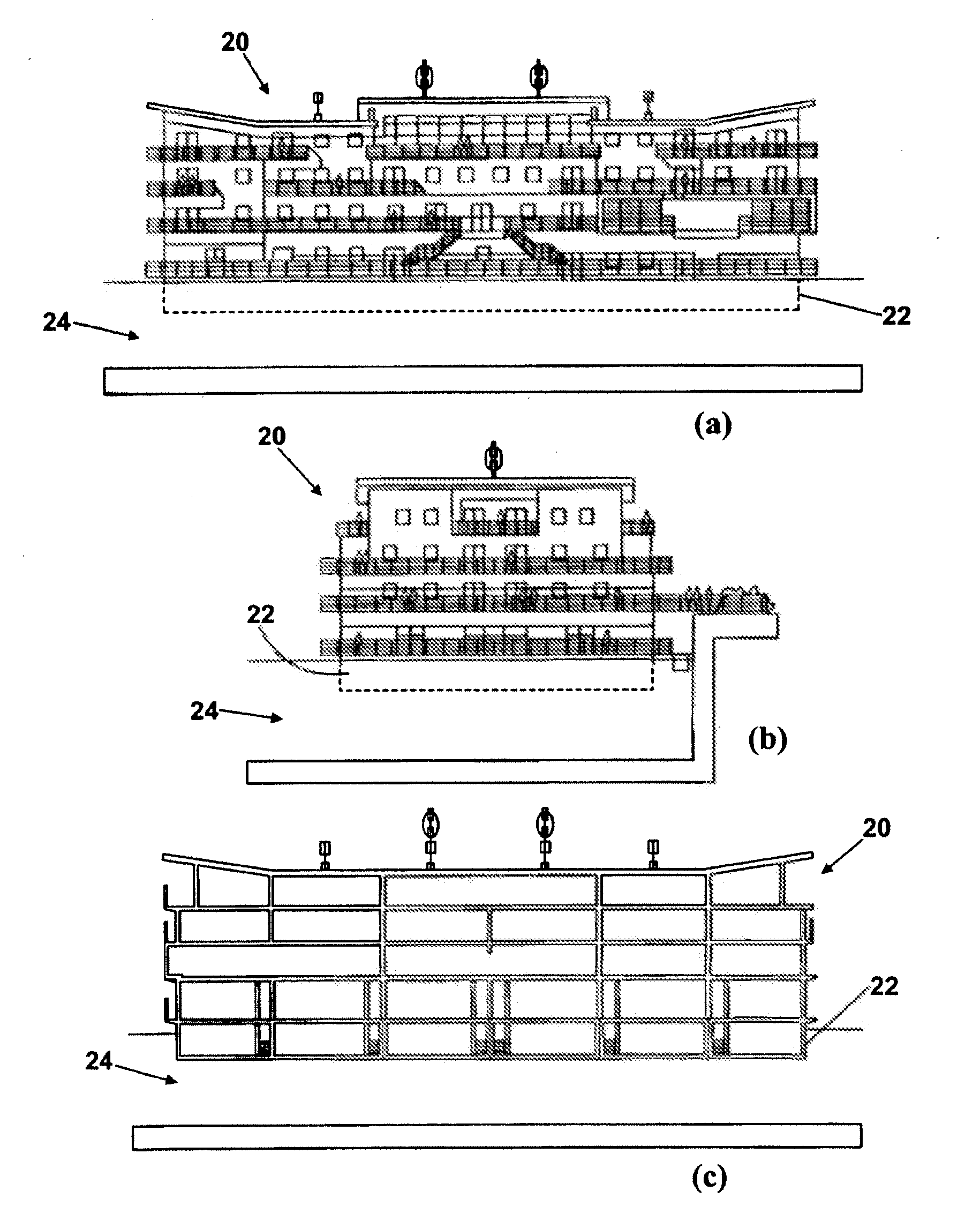
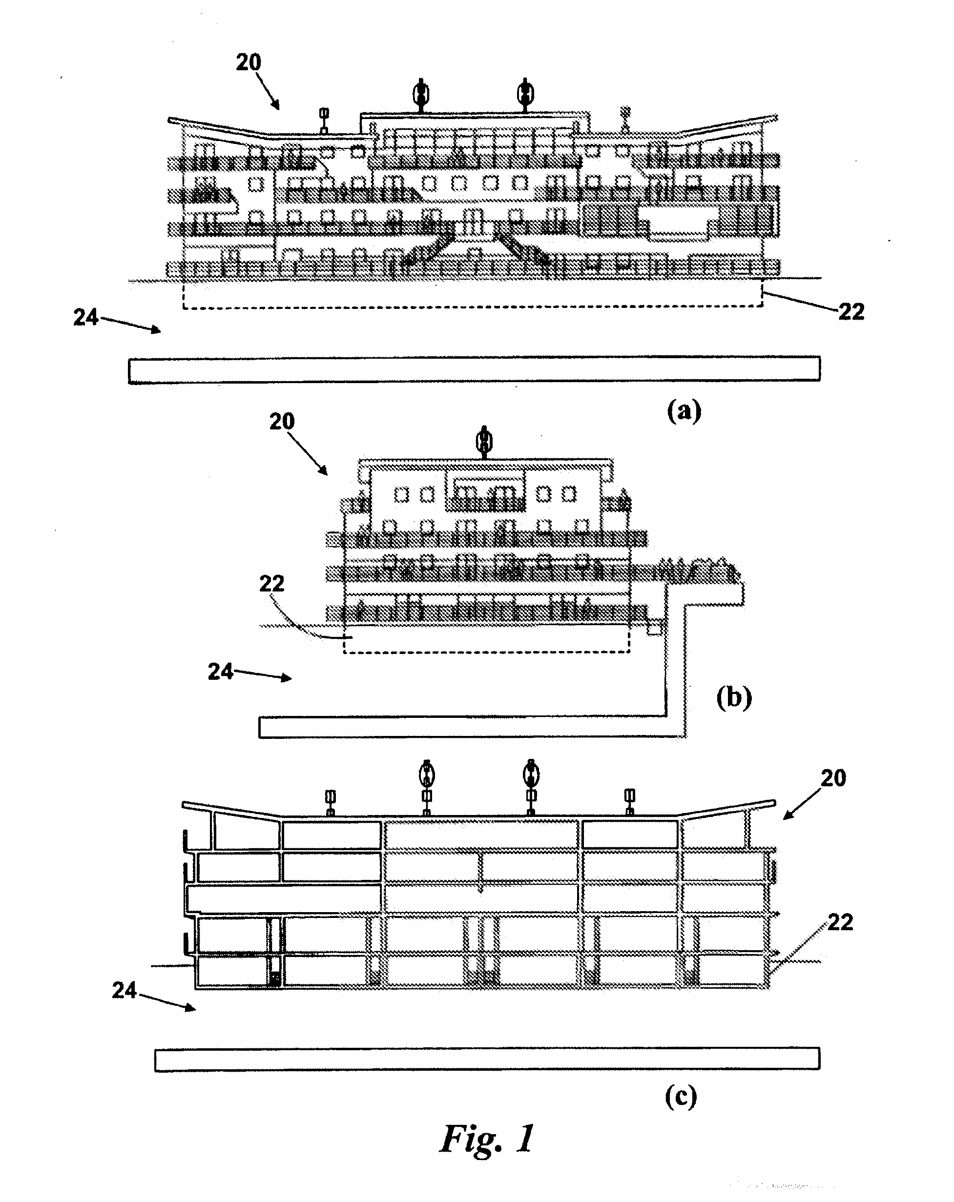
[0085]FIGS. 1 (a) to 1 (c) show a building according to the present invention. The building comprises, in broad terms, a superstructure 20 which is built atop a buoyant basement structure 22 which floats in a body of water 24, such as river, dock, harbour, lake, sea and so on. The buoyant basement structure 22 therefore provides a floating base upon which the superstructure 20 is constructed and supported. The basement structure 22 is shown partially submerged in water in FIGS. 1 (a) to 1 (c).

[0086]In this example, the building is arranged to provide hotel facilities, including bedrooms, bathrooms, communal areas such as leisure facilities and restaurants, and service areas such as kitchens, laundries and plant rooms. Additionally, access routes between the various rooms and spaces are provided.

[0087]Although the example of a floating hotel will be used throughout the remainder of this description, it will be appreciated that such a building could be used for substantially any funct...


PUM


Abstract

A floating base for a building, the base comprising at least one buoyant basement unit defining a basement level, and a reinforced concrete transfer slab atop the or each basement unit. The basement level provides habitable or functional space for the building, and the transfer slab has at least one access opening giving access to the basement level. Preferably, the base comprises at least two buoyant basement units, wherein each of the basement units is independently buoyant for assembly with at least one other basement unit during construction of the base, said basement units thereby assuming a final position in which said units are closely adjacent or in contact to define a basement level comprising two or more of said units. The invention also extends to a method for constructing a floating base for a building, and a method for launching a buoyant basement unit.

Description

CROSS REFERENCE TO RELATED APPLICATIONS[0001]This application is a divisional of U.S. Non-Provisional Application No. 12 / 991,774 filed Nov. 9, 2010, still pending, which is the National Stage of International Application No. PCT / GB2009 / 050498, filed May, 11, 2009.FIELD OF THE INVENTION[0002]The present invention relates to floating buildings. In particular, but not exclusively, the invention relates to a buoyant basement structure for a floating building, and a method for constructing such a structure.BACKGROUND TO THE INVENTION[0003]In modern urban environments, the development and construction of large buildings for residential, commercial, leisure or industrial use can often be beset with problems.[0004]For example, suitable land for development can be difficult to find. In many cities, large pieces of development land seldom become available, which can restrict the choice of location. However, particularly for commercial developments such as hotels, location is an extremely impo...

Claims


Application Information

Patent Timeline
Patent Type & Authority Applications(United States)
IPC IPC(8): B63B35/44B63B5/14B63B35/34B63B35/38
CPCE04H3/02E04H1/04
Inventor NELSON, CARL R.
Owner LIZZANO
Why Eureka
Try Eureka