Electrical connector assembly, test lead assembly therefor, and associated method

a technology of electrical connectors and lead assemblies, applied in the direction of coupling device connections, conductor screwing into other, instruments, etc., can solve the problems of deformation of spade connectors and/or conductors, affecting the performance of electrical connectors, etc., to achieve quick and easy testing

Active Publication Date: 2011-06-16
WESTINGHOUSE ELECTRIC CORP
View PDF18 Cites 15 Cited by
  • Summary
  • Abstract
  • Description
  • Claims
  • Application Information

AI Technical Summary

Benefits of technology

[0008]These needs and others are met by embodiments of the disclosed concept, which are directed to a test lead assembly for electrical connector assemblies, such as terminal boards. Among other benefits, the test lead assembly maintains the integrity of the primary electrical connections of the terminal board by enabling them to be relatively quickly and easily tested, without requiring separate tools and without requiring the primary electrical connections to be loosened or otherwise altered or adjusted.

Problems solved by technology

This process is labor-intensive and time-consuming, and can degrade the spade connectors and / or conductors (e.g., without limitation, wires; cables) over time.
The process can also cause the threads of the terminal screws to seize up from frequent loosening and tightening, the heads of the screws can break off and / or a variety of other problems can ensue.
The foregoing undesirably results in extensive downtime and costly repair work (e.g., without limitation, drilling out the remainder of the fractured screw; replacing the entire terminal board).

Method used


Image

  • Electrical connector assembly, test lead assembly therefor, and associated method
  • Electrical connector assembly, test lead assembly therefor, and associated method
  • Electrical connector assembly, test lead assembly therefor, and associated method

Examples


Embodiment Construction

[0022]Directional phrases used herein, such as, for example, clockwise, counterclockwise, top, bottom and derivatives thereof, relate to the orientation of the elements shown in the drawings and are not limiting upon the claims unless expressly recited therein.

[0023]As employed herein, the statement that two or more parts are “coupled” together shall mean that the parts are joined together either directly or joined through one or more intermediate parts.

[0024]As employed herein, the term “number” shall mean one or an integer greater than one (i.e., a plurality).

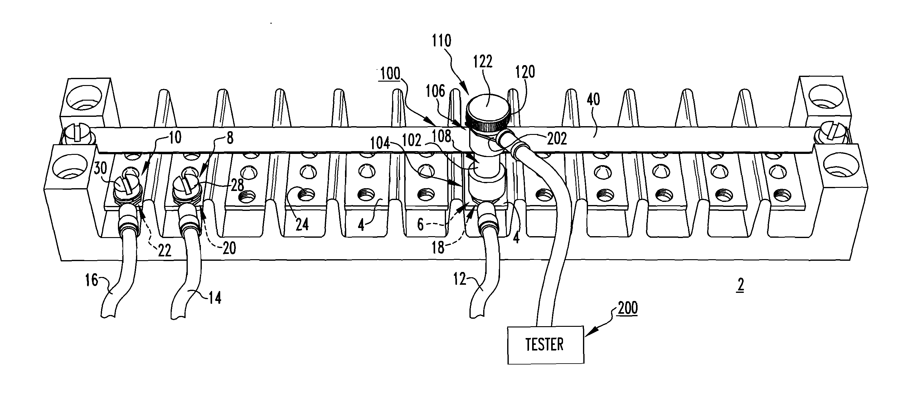
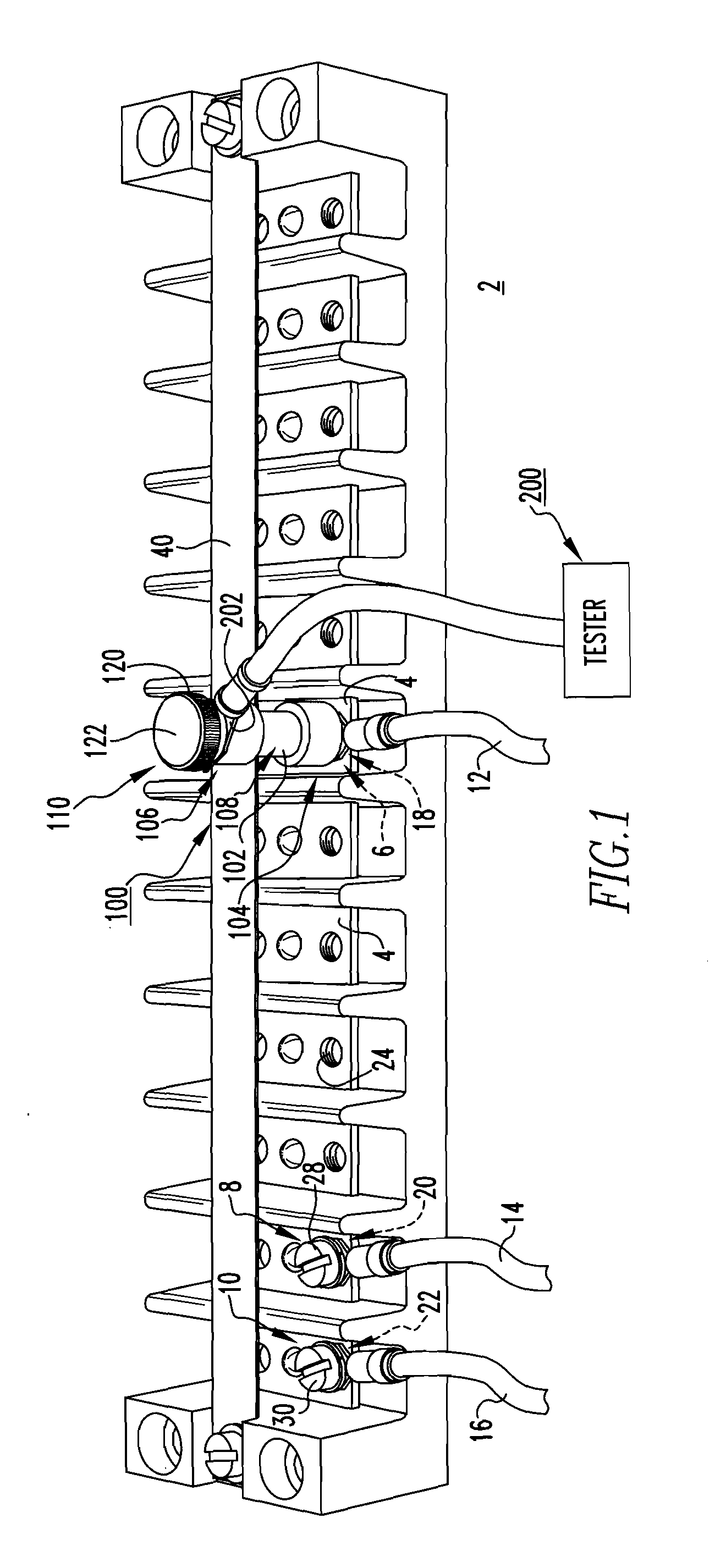
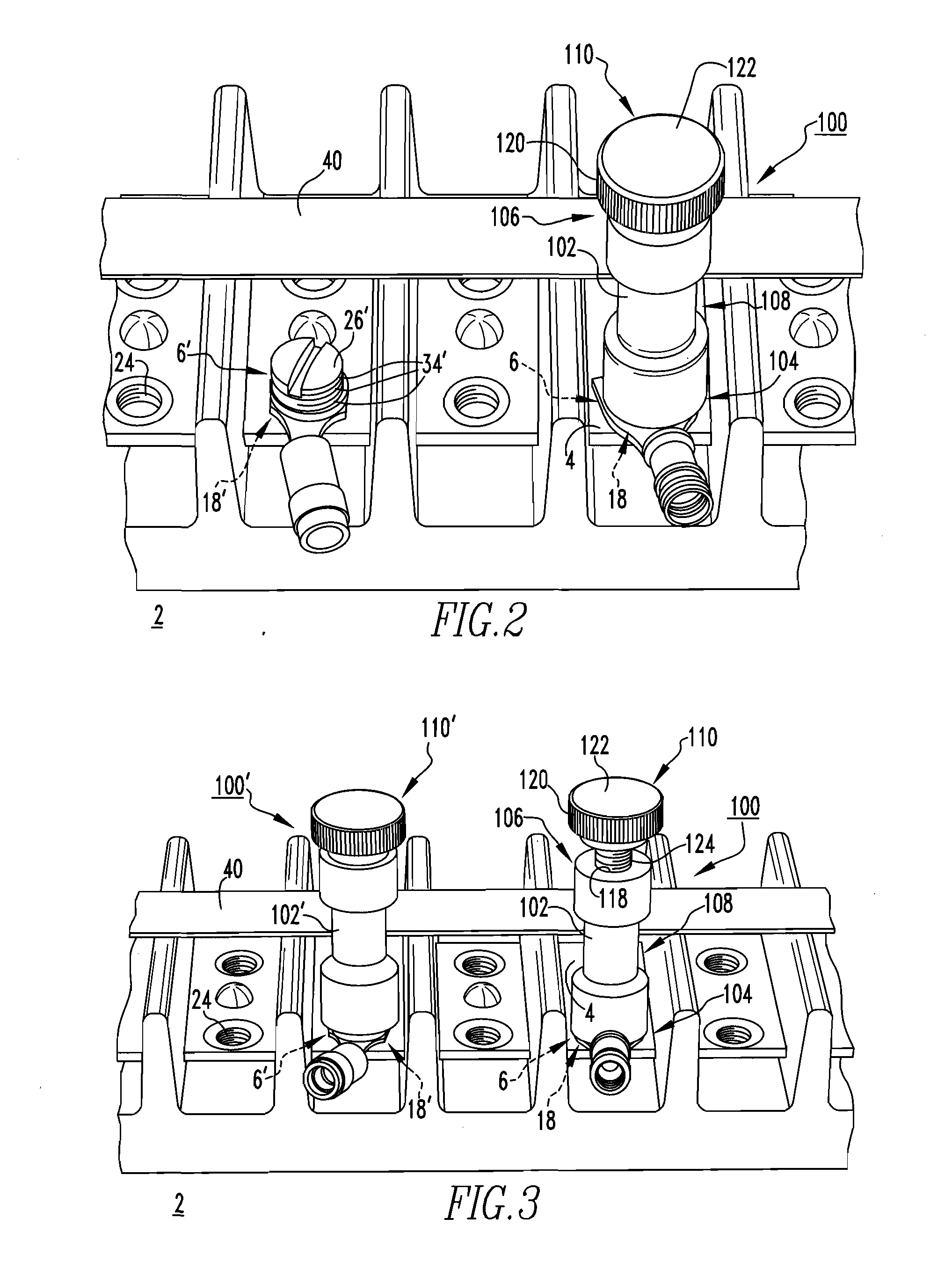
[0025]FIG. 1 shows a test lead assembly 100 for an electrical connector assembly such as, for example and without limitation, the terminal board 2, which is shown. The terminal board 2 includes an electrically conductive generally planar member 4. It will be appreciated that the generally planar member 4 may be divided into segments separated by electrically isolative barriers or separators, as shown for example in FIG. 4. A ...


PUM

PropertyMeasurementUnit
electricallyaaaaaaaaaa
diameteraaaaaaaaaa
electrically conductiveaaaaaaaaaa

Abstract

A test lead assembly is provided for an electrical connector assembly, such as a terminal board. The terminal board includes a generally planar member and a number of fasteners, such as terminal screws, which are structured to fasten and electrically connect electrical conductors to the generally planar member. The test lead assembly includes an extension member having first and second opposing ends, and an intermediate portion extending therebetween. The first end is fastened to the enlarged head of a corresponding one of the terminal screws. A connection element is disposed at or about the second end of the extension member. In one embodiment the connection element is a thumb screw that electrically connects a test element to the extension member. The test lead assembly enables the terminal board to be tested, without loosening or otherwise disturbing the electrical connections of the terminal board. An associated method is also disclosed.

Description

BACKGROUND[0001]1. Field[0002]The disclosed concept relates generally to electrical apparatus and, more particularly to electrical connector assemblies, such as terminal boards. The disclosed concept also relates to test lead assemblies. The disclosed concept further relates to methods of providing test lead assemblies for electrical connector assemblies.[0003]2. Background Information[0004]One non-limiting example of an electrical connector assembly is a terminal board. Terminal boards, which are sometimes referred to as terminal strips or terminal blocks, provide a convenient mechanism for connecting a plurality of electrical conductors (e.g., without limitation, wires; cables), thereby electrically connecting various associated electrical circuits, equipment and / or components.[0005]In some applications, the conductors (e.g., without limitation, wires; cables) are secured to the terminal board directly, for example, by fastening a stripped portion of each wire beneath the enlarged...

Claims


Application Information

Patent Timeline
Patent Type & Authority Applications(United States)
IPC IPC(8): H01R11/18H01R43/00
CPCG01R1/0408H01R4/56H01R2101/00Y10T29/49174H01R9/22H01R11/01H01R2201/20H01R4/30
Inventor KISIC, JAMES A.MCCASLIN, SAMUEL C.
Owner WESTINGHOUSE ELECTRIC CORP
Why Eureka
Try Eureka