Digital, Small Signal and RF Microwave Coaxial Subminiature Push-on Differential Pair System

a technology of differential pair and small signal, which is applied in the direction of coupling device connection, two-part coupling device, three-pole connection, etc., can solve the problem of impracticality of coupling nut use, and achieve the effect of improving electrical performance and easy production

Active Publication Date: 2011-06-23
CORNING OPTICAL COMM LLC
View PDF39 Cites 70 Cited by
  • Summary
  • Abstract
  • Description
  • Claims
  • Application Information

AI Technical Summary

Benefits of technology

[0012]Accordingly, a simple connector is disclosed herein that can easily be produced from a small number of components. The connector preferably forms a reliable electrical RF microwave connection with low mechanical engage and disengage forces. Furthermore, the connector disclosed herein provides an improved electrical performance up to 40 GHz.

Problems solved by technology

However, when confronted with two electrical conductors in the system, the use of a coupling nut becomes impractical.

Method used


Image

  • Digital, Small Signal and RF Microwave Coaxial Subminiature Push-on Differential Pair System
  • Digital, Small Signal and RF Microwave Coaxial Subminiature Push-on Differential Pair System
  • Digital, Small Signal and RF Microwave Coaxial Subminiature Push-on Differential Pair System

Examples


Embodiment Construction

[0040]Reference will now be made in detail to the present preferred embodiment(s) of the invention, examples of which are illustrated in the accompanying drawings. Whenever possible, the same reference numerals will be used throughout the drawings to refer to the same or like parts.

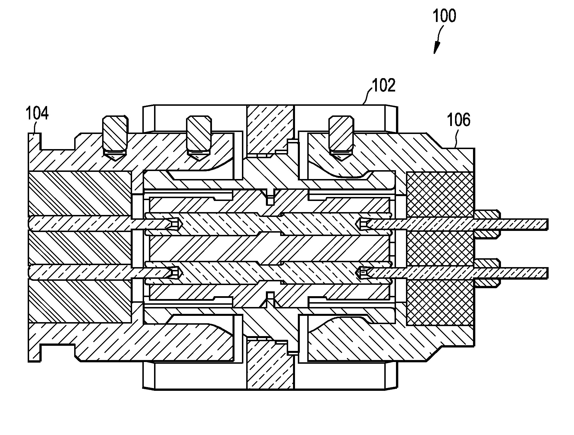
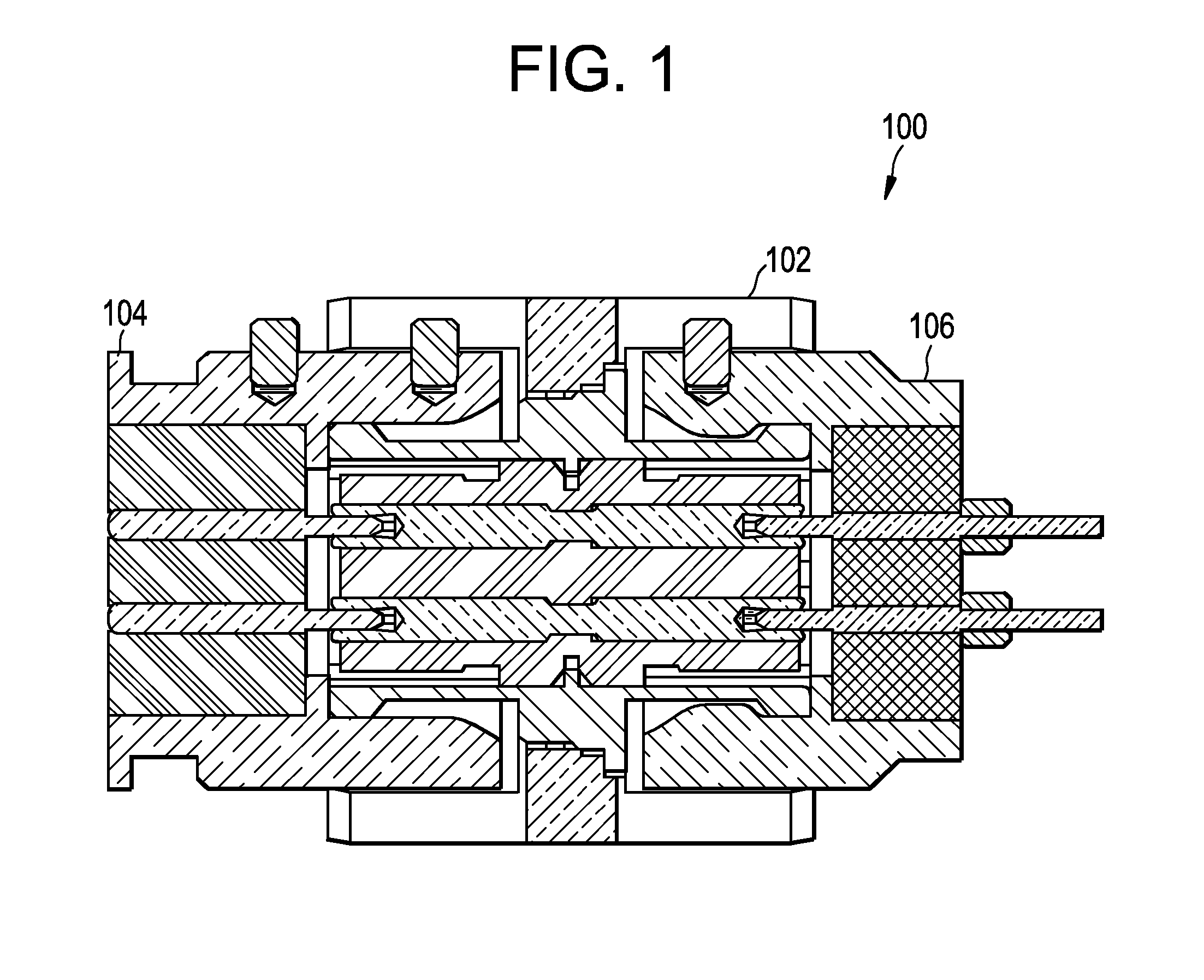
[0041]Referring to FIGS. 1-12, a connector assembly 100 includes a connector sleeve 102, a first connector 104, and a second connector 106. Generally, the connector assembly 100 allows for the connection, and in particular, the blind mating of the first connector 104 and the second connector 106. As can be seen from the figures, as well as being described above, the connector assembly 100 provides for a quick way to engage and disengage differential pair interconnects that use push-on technology.

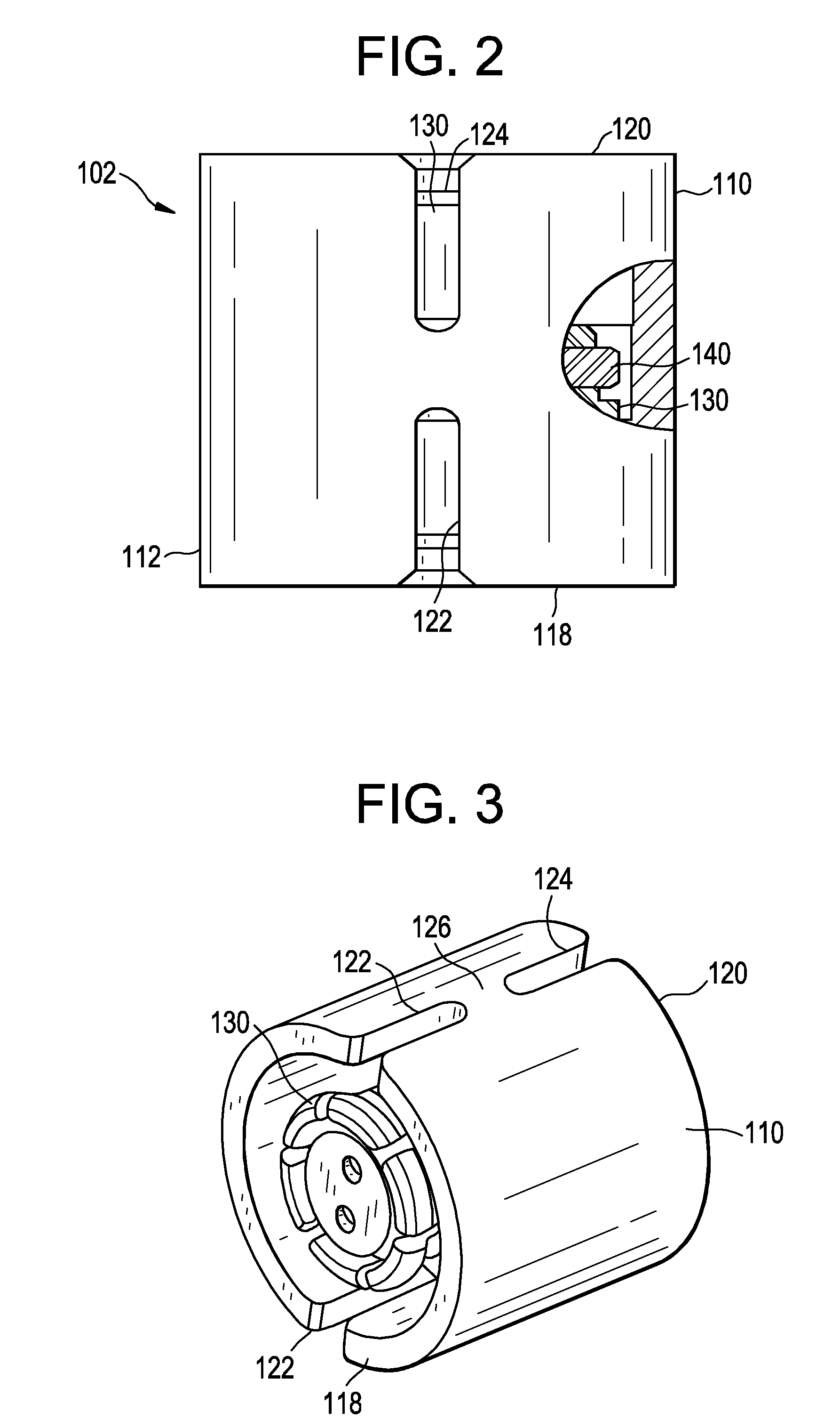
[0042]Turning now to FIGS. 2-5, the connector sleeve 102, which is a push-on high frequency differential connector sleeve, includes an outer body 110, an outer surface 112, and inner surface 114, the inner surface...


PUM


Abstract

The differential pair system includes a push-on high frequency differential connector sleeve and push-on high frequency differential connector. The system allows for blind mating of the two components, using a keying system for the two electrical conductors to be axially and radially aligned.

Description

CROSS-REFERENCE TO RELATED APPLICATIONS[0001]This application claims the benefit of, and priority to U.S. Provisional Patent Application No. 61 / 288,493 filed on Dec. 21, 2009 entitled, “Digital, Small Signal and RF Microwave Coaxial Subminiature Push-on Differential Pair System”, the content of which is relied upon and incorporated herein by reference in its entirety.BACKGROUND OF THE INVENTIONField of the Invention[0002]The present invention relates generally to a digital, small signal and RF microwave frequency coaxial differential pair connector sleeve and connectors that includes a push-on interface.TECHNICAL BACKGROUND[0003]Within the technical field of digital, small signal and RF microwave frequency coaxial connectors there exists a sub-set of connector interface designs engageable without the aid of external coupling mechanisms such as split keying dielectric components. These interconnect systems are known in the industry as Twin axial TNC's and BNC's. Twin axial, different...

Claims


Application Information

Patent Timeline
Patent Type & Authority Applications(United States)
IPC IPC(8): H01R9/05
CPCH01R13/6277H01R13/6581H01R31/06H01R13/6456H01R2105/00H01R24/568
Inventor FLAHERTY, THOMAS E.HART, DENNIS FRANCIS
Owner CORNING OPTICAL COMM LLC
Why Eureka
Try Eureka