Dispensing container

a container and container body technology, applied in the field of containers, can solve the problem of no secondary mechanism to prevent children from accessing the container, and achieve the effect of facilitating the movement of the inner tray and facilitating the deflection of the flexible locking button

Active Publication Date: 2011-07-14
R J REYNOLDS TOBACCO COMPANY
View PDF78 Cites 140 Cited by
  • Summary
  • Abstract
  • Description
  • Claims
  • Application Information

AI Technical Summary

Benefits of technology

In certain embodiments, the projection of the outer casing has a beveled surface facing toward the open end of the outer casing. The inner tray may include at least one rib extending between the first segment and the second segment of the flexible locking tab, the rib having a beveled surface positioned to engage the beveled surface of the projection of the outer casing to facilitate movement of the inner tray between the dispensing position and the closed and locked position. Still further, in certain embodiments, the at least one projection further comprises a surface transverse to the top or bottom of the outer casing and positioned to engage the second segment of the flexible locking tab of the inner tray when the inner tray is in the closed and locked position. The inner tray may also include at least one rib extending between the first segment and the second segment of the flexible locking tab and having a surface positioned to engage the depressible button of the outer casing to facilitate deflection of the flexible locking button when the inner tray is in the closed and locked position.
In another embodiment, the second end of the inner tray comprises a lip extending transverse to the longitudinal axis of the inner tray, the lip positioned to abut the top or bottom of the outer casing. A depression is typically formed between the lip of the inner tray and the top or bottom of the outer casing for facilitating grasping of the inner tray.

Problems solved by technology

Further, if an adult user fails to place the cap in the properly secured position, there is no secondary mechanism for preventing access by a child.

Method used


Image

  • Dispensing container
  • Dispensing container
  • Dispensing container

Examples


Embodiment Construction

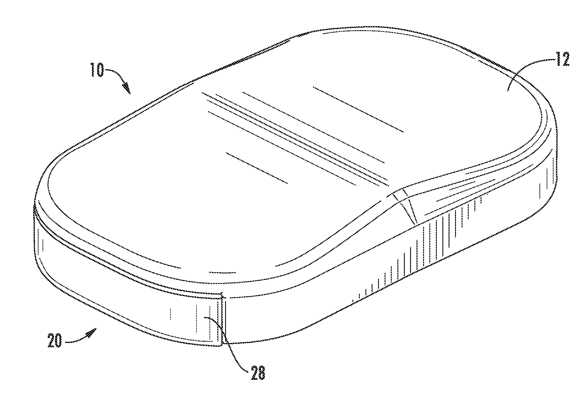
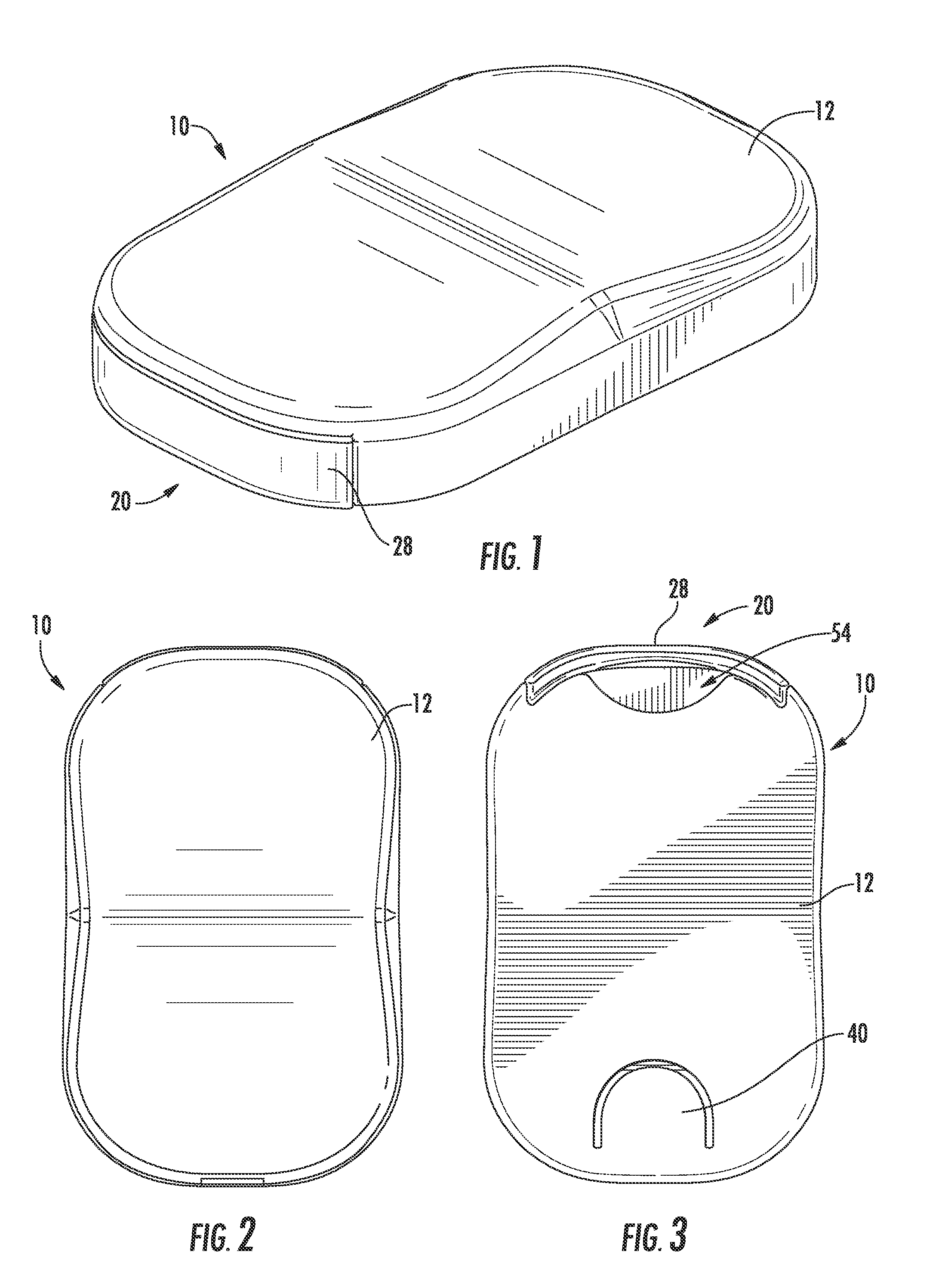
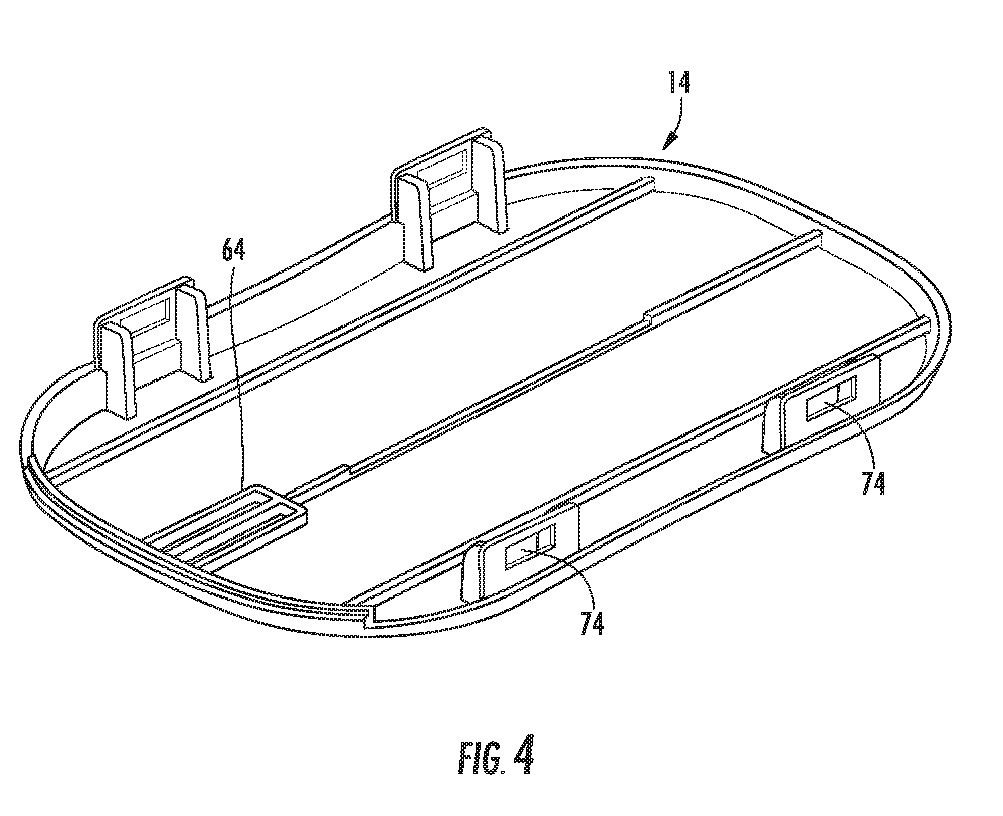
The present invention now will be described more fully hereinafter with reference to certain preferred embodiments. These embodiments are provided so that this disclosure will be thorough and complete, and will fully convey the scope of the invention to those skilled in the art. Indeed, the invention may be embodied in many different forms and should not be construed as limited to the embodiments set forth herein; rather, these embodiments are provided so that this disclosure will satisfy applicable legal requirements. As used in the specification, and in the appended claims, the singular forms “a”, “an”, “the”, include plural referents unless the context clearly dictates otherwise. Use of the term “transverse” does not strictly require a 90° angle between the transverse elements, but encompasses elements positioned at an angle that deviates from 90° by a relatively small margin (e.g., a deviation of no more than about 20 degrees).

The container embodiments described in the present a...


PUM


Abstract

The invention provides a dispensing container including an outer casing having an open end, a top, a bottom, sidewalls extending between the top and bottom, and an interior compartment, wherein the outer casing further includes a depressible button in the top or bottom and at least one projection adjacent to the depressible button that extends into the interior compartment; and an inner tray slidably received within the interior compartment of the outer casing. The inner tray includes a first end received within the outer casing, an opposing second end extending outwardly from the outer casing, a flexible locking tab positioned proximal to the first end, and an opening adjacent to the flexible locking tab, the flexible locking tab including a first segment extending toward the second end of the inner tray and a second segment extending transversely from the first segment. The second segment is positioned to engage the projection.

Description

FIELD OF THE INVENTIONThe present invention relates to containers and methods of use thereof. More particularly, the invention relates to containers that provide dispensing or dosing of the stored product and a locking mechanism.BACKGROUND OF THE INVENTIONVarious types of containers for dispensing solid objects, particularly solid products intended for human consumption, are known in the art. Such containers are often characterized by a hand-held size that can be easily stored and transported. Exemplary consumable products that are often packaged in such containers include pharmaceutical compositions, oral tobacco products, snacks, mints, gums, breath strips, candy, and the like.Certain consumable products, such as pharmaceutical products, require containers having a certain level of child resistance. Traditionally, pills have been packaged in a bottle having a cap that can only be removed by applying downward pressure while twisting the cap. However, this type of child resistance h...

Claims


Application Information

Patent Timeline
Patent Type & Authority Applications(United States)
IPC IPC(8): B65D45/16
CPCB65D83/0409B65D2215/04B65D85/60
Inventor BAILEY, RYAN A.GELARDI, JOHN A.
Owner R J REYNOLDS TOBACCO COMPANY
Why Eureka
Try Eureka