Welding or cutting device

a cutting device and cutting edge technology, applied in the direction of arc welding apparatus, laser beam welding apparatus, gas flame welding apparatus, etc., can solve the problems of reducing affecting the service life of the device, so as to improve the measurement accuracy, improve the service life, and improve the effect of the cutting speed

Active Publication Date: 2011-10-13
IHT AUTOMATION
View PDF7 Cites 6 Cited by
  • Summary
  • Abstract
  • Description
  • Claims
  • Application Information

AI Technical Summary

Benefits of technology

To reinforce the inductance, it is practical if the sensor device has a sleeve consisting at least in part of soft-magnetic material, on the outside of which sleeve the at least one magnetic coil is disposed. The sleeve preferably extends over a part of the length of the pipe and over the majority of the length of the nozzle. By means of this measure, the magnetic field lines exit from the sensor device close to the work piece, so that the measurement accuracy is increased. The sleeve can be in one piece. However, it is preferred that the sleeve is composed of multiple pieces, with a first part disposed around the pipe, and a second part disposed around the nozzle. In this connection, the first part carries the magnetic coil or the magnetic coils. In order to achieve a good magnetic flow between the two parts, it is preferred that the two parts are disposed to overlap, and preferably are screwed onto one another. A screw connection by means of

Problems solved by technology

At the torch tip, high temperatures are often reached, which can cause the insulation of the windings of the magnetic coil or the magnetic coils to melt.
In the case of other welding or cutting devices, there is also the risk that a mag

Method used


Image

  • Welding or cutting device
  • Welding or cutting device

Examples


Embodiment Construction

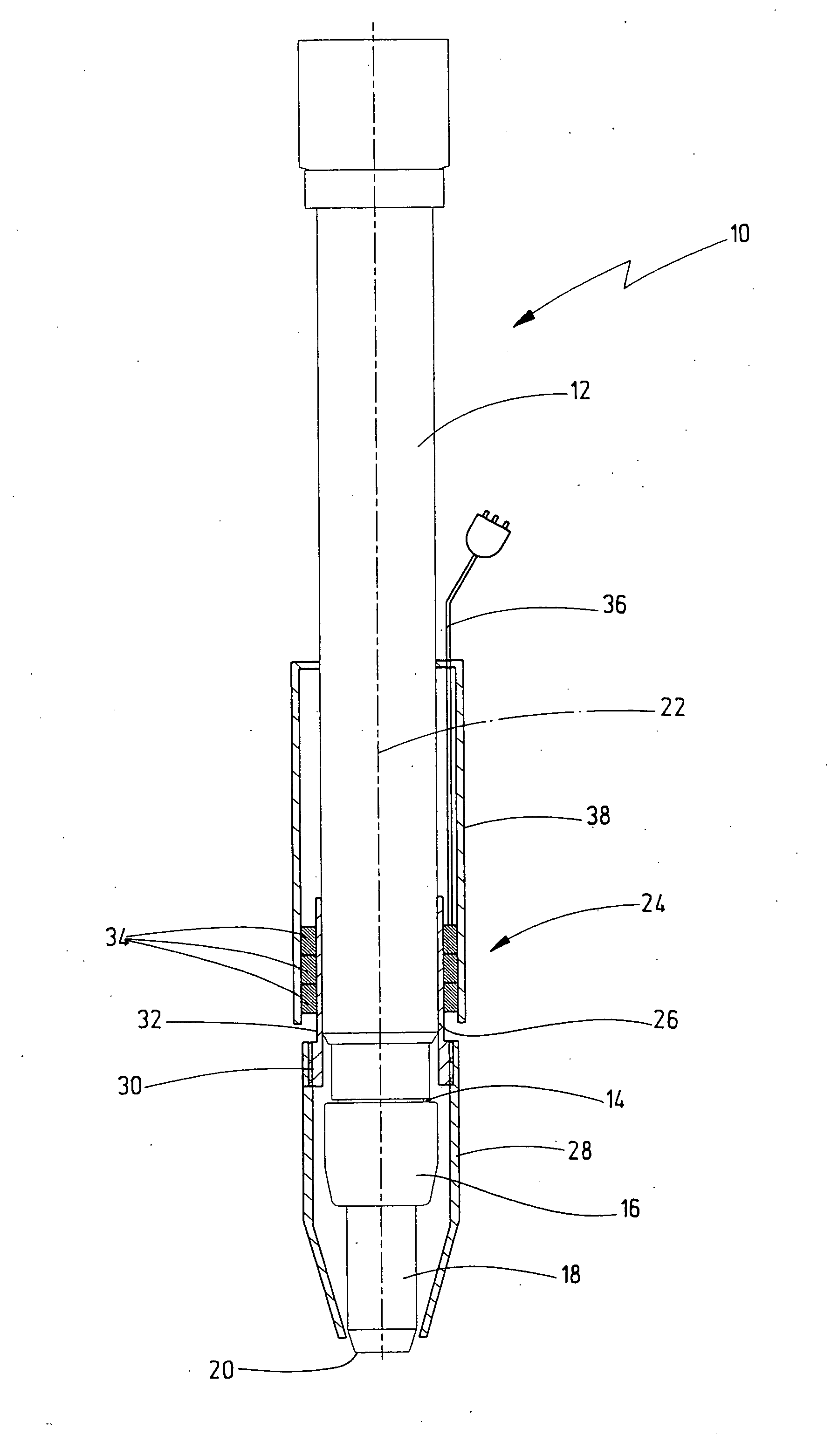
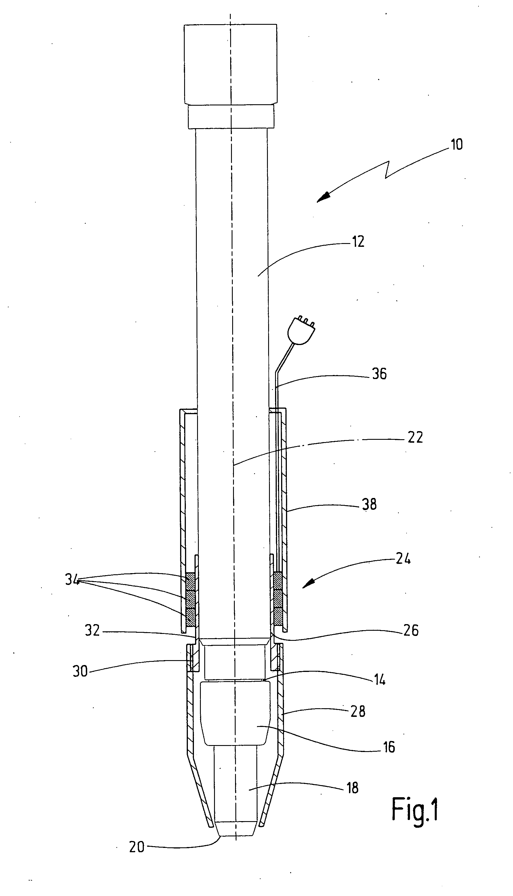
Referring now in detail to the drawings, the cutting torch 10 shown in FIG. 1 has a torch pipe 12 having a standardized outside diameter of 32 mm, in which the lines for feed of the torch gases run. At the lower end 14 of torch pipe 12, a torch nozzle 18, the free end of which forms torch tip 20, is attached by means of a nut 16. The flame that forms during combustion of the torch gases exits from torch tip 20. Torch pipe 12, nut 16, and torch nozzle 18 are configured to be essentially rotation-symmetrical with regard to a longitudinal torch axis 22.

A sensor device 24, which has a sleeve composed of soft-magnetic material, is pushed onto torch pipe 12 and torch nozzle 18, on the outside. The sleeve consists of a first part 26, which is pushed onto torch pipe 12 and attached there, and a second part 28, which is connected with the first part 26 by means of a screw connection 30, and extends over the lower part of torch pipe 12 as well as over the majority of the length of torch nozzl...


PUM

PropertyMeasurementUnit
Lengthaaaaaaaaaa
Electric potential / voltageaaaaaaaaaa
Distanceaaaaaaaaaa

Abstract

A welding or cutting device for welding or cutting electrically conductive work pieces has a pipe that accommodates feed lines, a nozzle for exit of a welding or cutting jet, such as a flame, for example, disposed at an end of the pipe, forming a device tip with its free end, and an inductive sensor device for measuring the distance between the device tip and the work piece. The sensor device has at least one magnetic coil, the windings of which run about a longitudinal device axis. The sensor device is a separate module, which is pushed onto the pipe and/or the nozzle, and releasably connected with the pipe and/or the nozzle.

Description

CROSS REFERENCE TO RELATED APPLICATIONSApplicant claims priority under 35 U.S.C. 119 of German Application No. 20 2010 004 903.2 filed Apr. 12, 2010, the disclosure of which is incorporated by reference.BACKGROUND OF THE INVENTION1. Field of the InventionThe invention relates to a welding or cutting device for welding or cutting electrically conductive work pieces, having a pipe that accommodates feed lines, a nozzle for exit of a welding or cutting jet such as a flame, disposed at an end of the pipe, forming a device tip with its free end, and an inductive sensor device for measuring the distance between the device tip and the work piece. The sensor device has at least one magnetic coil, the windings of which run about a longitudinal device axis.2. The Prior ArtIn order to determine the distance between the tip of such a processing device, for example a cutting torch, and the work piece, it is known to provide the cutting torch with a sensor device that has one or more magnetic coi...

Claims


Application Information

Patent Timeline
IPC IPC(8): B23H1/00
CPCB23K5/22B23K26/422B23K9/0956B23K26/702
Inventor NACHBARGAUER, KURT
Owner IHT AUTOMATION
Why Eureka
Try Eureka