Fish passage apparatus with flow restriction and method

a flow restriction and apparatus technology, applied in the field of fish passage apparatuses with flow restriction and methods, can solve the problems of ineffective head heights less than 90 feet, methods are also problematic, and fish passing through, so as to reduce back pressure, less pressure, and generate more electricity

Active Publication Date: 2011-11-17
MILLARD KENNETH T
View PDF2 Cites 1 Cited by
  • Summary
  • Abstract
  • Description
  • Claims
  • Application Information

AI Technical Summary

Benefits of technology

[0032]It is the object of this invention to provide a fish passage apparatus that maintains a near constant flow and pressure on the fish or to only allow flows and pressure changes that are within a healthy range as determined by experts. Although, opening and closing the upper and lower valves quickly to gain the effect of water hammer or fluid inertia will generate more electricity; it may also cause pressure spikes and flow fluctuations that can be harmful to the fish by scaring them away or causing the water to flow too fast to swim up. To prevent the pressure or flow in the connecting tubes from changing too rapidly a means for restricting the flow will be introduced into the working tube. The flow can be restricted by having a variable valve in the working tube that opens wider as flows decrease and closes as flows increase to maintain a near constant flow rate. Another means for restricting flow can be changing the diameter of the working tube entirely. A larger working tube would allow the water to flow for a longer time and have decreased back pressure therefore less pressure could build in the connecting tubes. A smaller diameter working tube would decrease fluid flow in the connecting tube therefore, increasing the velocity of the water flowing into the working tubes and magnifying the effect of water hammer or fluid inertia. In most instances the means for generating electricity from the water in the working tube will pull most of the energy out of the flowing water and will be a flow restrictor in itself.

Problems solved by technology

However, turbine based systems do not allow for fish migration beyond the dams or often injure fish passing through them.
Unfortunately, these methods are also problematic due to passage delays, increases in dissolved gasses, fish de-scaling, fish disorientation, increased predation, injury and so forth.
Further, they are only effective with head heights less than about 90 feet.
For dams with a head of more than 90 feet, fish must be trapped and transported around or lifted over the dam due to excessive mortality rates and the inability of fish to completely climb the ladders.
For a traditional generator it may also be important to rectify the water flow so that the back-flowing water does not flow against the turbine and potentially cause damage.
Experimentation has shown that this will likely require the valves to open and close less quickly, which will compromise to some extent the advantage described above in power generation.

Method used


Image

  • Fish passage apparatus with flow restriction and method
  • Fish passage apparatus with flow restriction and method
  • Fish passage apparatus with flow restriction and method

Examples


Embodiment Construction

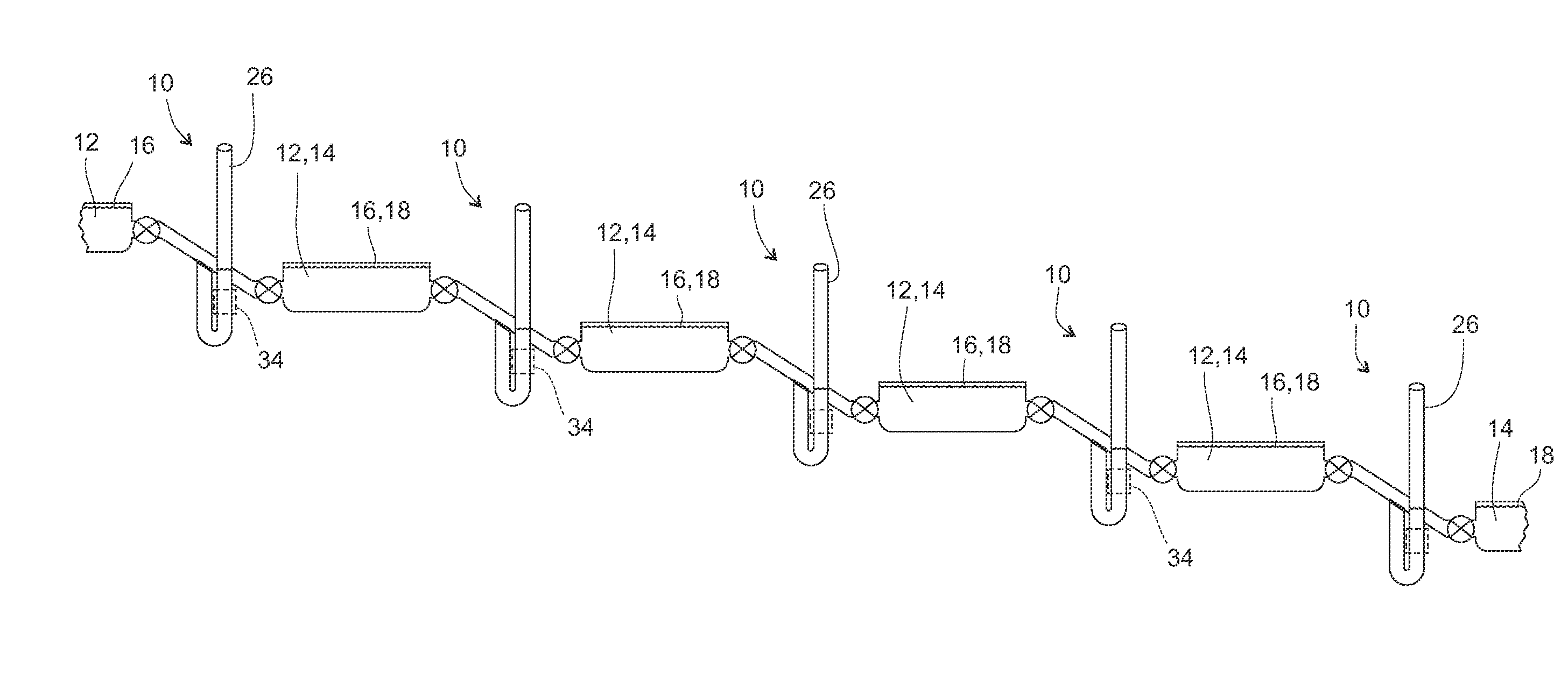
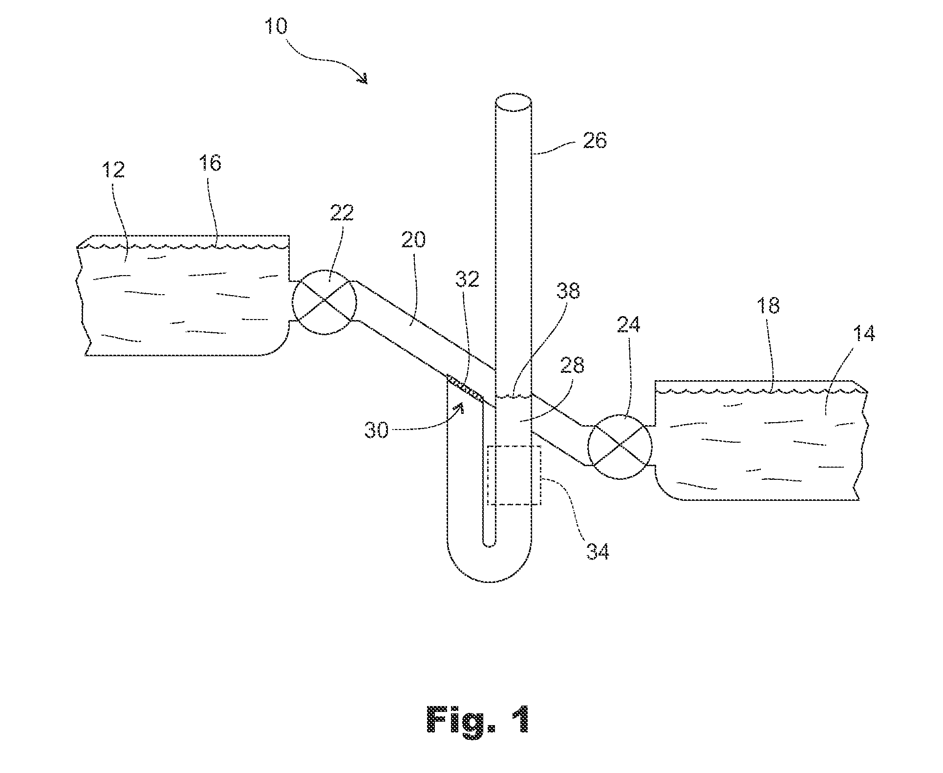
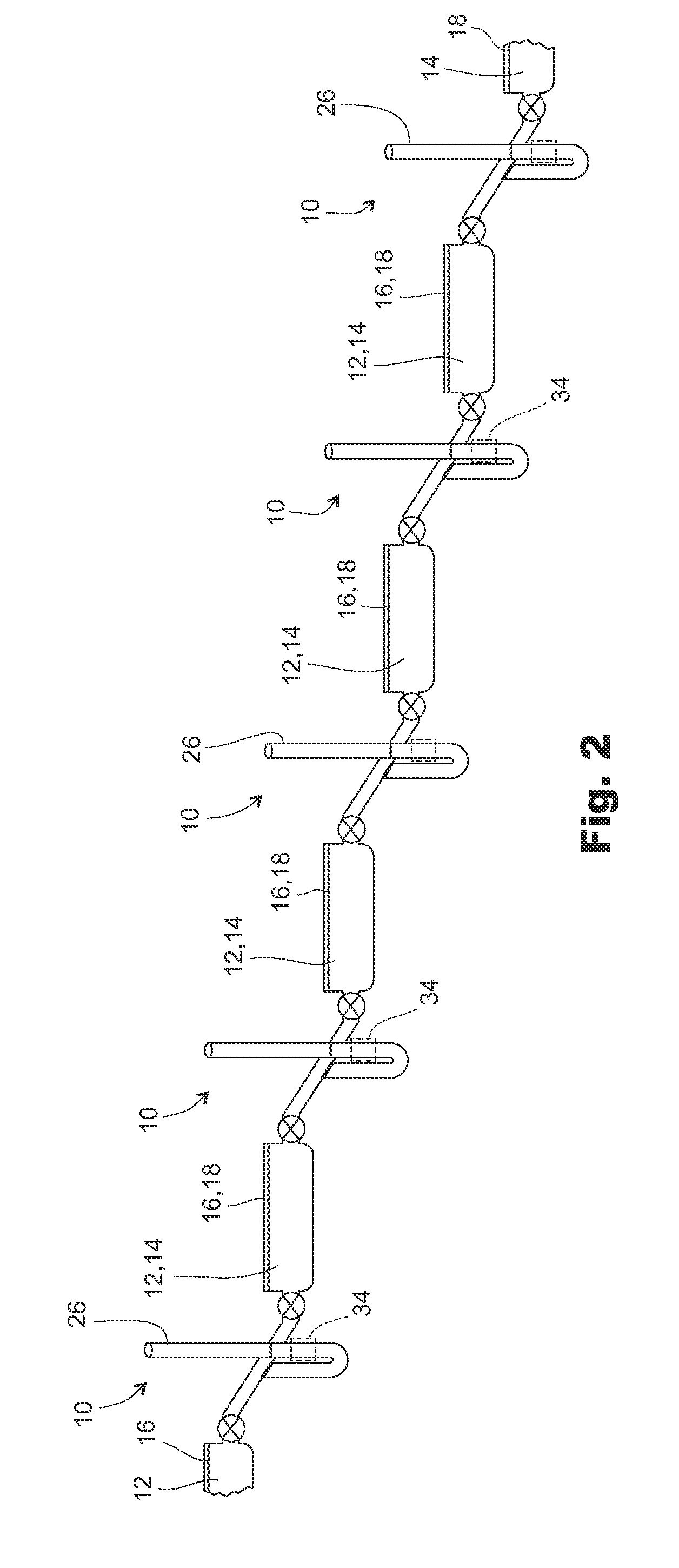
[0023]As shown in FIG. 1, the fish passage apparatus 10 of the present invention for fish passage between water bodies 12, 14 of different heights with different water levels 16, 18 comprises a connecting tube 20 providing fluid communication between upper and lower water bodies 12, 14, an upper valve 22 in the connecting tube 20 adapted to control flow of water to or from the upper water body 12, a lower valve 24 in the connecting tube 20 adapted to control flow of water to or from the lower water body 14, and a working tube 26 containing a column of water 28 with a surface level 38 opening into the connecting tube 20 between the upper and lower valves 22, 24 a working portion of which working tube 26 extends functionally vertical to above the water level 16 of the upper water body 12 and to below the water level 18 of the lower water body 14 and is vented at its top such that water can flow freely in and out of the working tube 26. A screen 30 covers the opening 32 of the working ...


PUM


Abstract

An improved fish passage apparatus is combined with hydroelectric power generation to facilitate migration of fish between water bodies of different heights with minimal injury or trauma to fish. It may also be optimized for power generation when fish are not moving through it. The fish passage apparatus comprises a connecting tube providing fluid communication between upper and lower water bodies, an upper valve in the connecting tube adapted to control flow of water to or from an upper water body, a lower valve in the connecting tube adapted to control flow of water to or from a lower water body, and a working tube opening into the connecting tube between the upper and lower valves a working portion of which extends functionally vertical to above a water level of the upper body of water and to below a water level of the lower body and is vented at its top such that water can flow freely in and out of the working portion. The working tube contains a means for restricting flow thereby increasing the safety to fish passing through the connecting tubes.

Description

[0001]This application is a continuation in part of that certain application filed May 8, 2009 under application Ser. No. 12 / 437,738 and claims the benefit thereof.BACKGROUND[0002]1. Field of the Invention[0003]This invention relates to tubes connected between two bodies of water of different elevations optimized for power generation, and more specifically to such a configuration adapted for fish migration between the bodies of water.[0004]2. Prior Art[0005]It is well known that power generators between bodies of water of different heights extract potential energy from the flow of water. Hydropower generation systems typically rely on water flow from dams through turbines that run generators. However, turbine based systems do not allow for fish migration beyond the dams or often injure fish passing through them. To avoid injury and death to fish passing dams, high cost systems are employed. Currently, the primary bypass methods are a series of pools as fish ladder apparatus for upst...

Claims


Application Information

Patent Timeline
Patent Type & Authority Applications(United States)
IPC IPC(8): E02B8/08
CPCF15B21/14E02B8/085Y02A40/60
Inventor MILLARD, KENNETH T.
Owner MILLARD KENNETH T
Why Eureka
Try Eureka