Piezoelectric vibrator, piezoelectric vibrator mounting body, and piezoelectric vibrator manufacturing method

a piezoelectric vibrator and mounting body technology, applied in the direction of piezoelectric/electrostrictive transducers, generators/motors, transducers, etc., can solve the problems of affecting the quality cracking in the connecting part between the through hole and the through electrode portion, etc., to achieve the effect of increasing the mechanical strength of the piezoelectric vibrator, reducing the resistance of electric current, and high affinity for sold

Inactive Publication Date: 2011-11-24
SII CRYSTAL TECH
View PDF4 Cites 2 Cited by
  • Summary
  • Abstract
  • Description
  • Claims
  • Application Information

AI Technical Summary

Benefits of technology

[0026]According to the invention, since the routing wiring portion and the bottom layer of the external electrode portion are integrally formed by the first metal, electrical resistance can be reduced. Further, since the second layer that is laminated on the surface of the bottom layer of the external electrode portion has a high affinity for the solder, a connection by solder can be performed in a reliable manner.
[0027]According to the piezoelectric vibrator, the piezoelectric vibrator mounting body and the piezoelectric vibrator manufacturing method according to the invention, since the external electrode portion and the through electrode portion are disposed in separate areas such that they are not overlapped with each other in the thickness direction of the first substrate, a concentration of stress generated in the through electrode portion via the external electrode portion is favorably reduced, and it is possible to increase mechanical strength of the piezoelectric vibrator, when the piezoelectric vibrator is mounted on the wiring substrate etc. Further, since it is possible to increase the mechanical strength of the piezoelectric vibrator when it is mounted on the wiring substrate etc., the piezoelectric vibrating reed inside the piezoelectric vibrator is sealed airtightly and it is possible to maintain quality of the piezoelectric vibrator provided in the piezoelectric vibrator mounting body.

Problems solved by technology

At this time, the stress concentrated on the through electrode portion may cause a crack in a connecting part between the through hole and the through electrode portion.
As a result, outside air circulates in the cavity, and this causes a problem in which a quality of the piezoelectric vibrator is affected.

Method used


Image

  • Piezoelectric vibrator, piezoelectric vibrator mounting body, and piezoelectric vibrator manufacturing method
  • Piezoelectric vibrator, piezoelectric vibrator mounting body, and piezoelectric vibrator manufacturing method
  • Piezoelectric vibrator, piezoelectric vibrator mounting body, and piezoelectric vibrator manufacturing method

Examples


first embodiment

[0036]Hereinafter, a piezoelectric vibrator and a piezoelectric vibrator mounting body according to a first embodiment of the invention will be described with reference to FIG. 1 to FIG. 4.

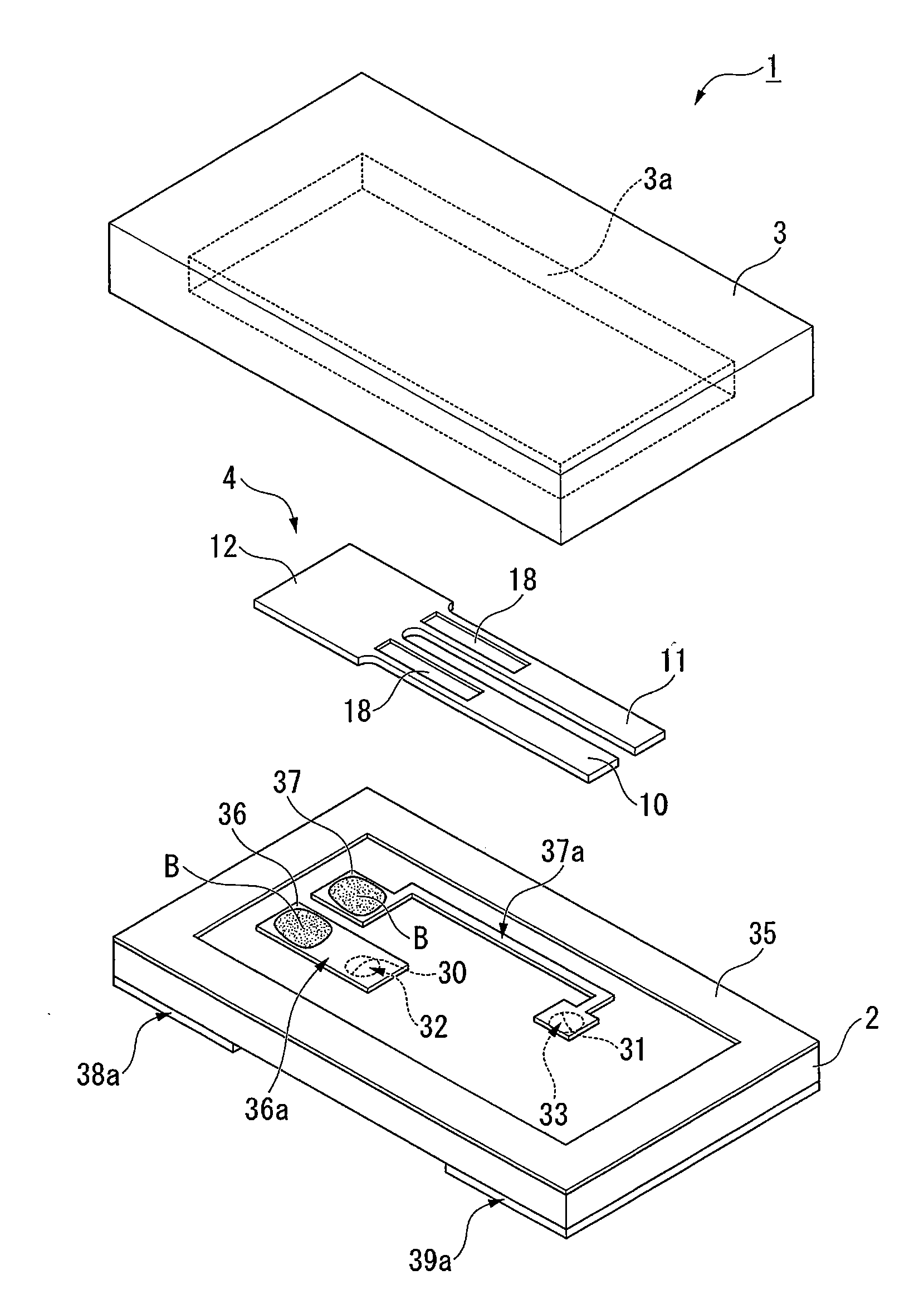
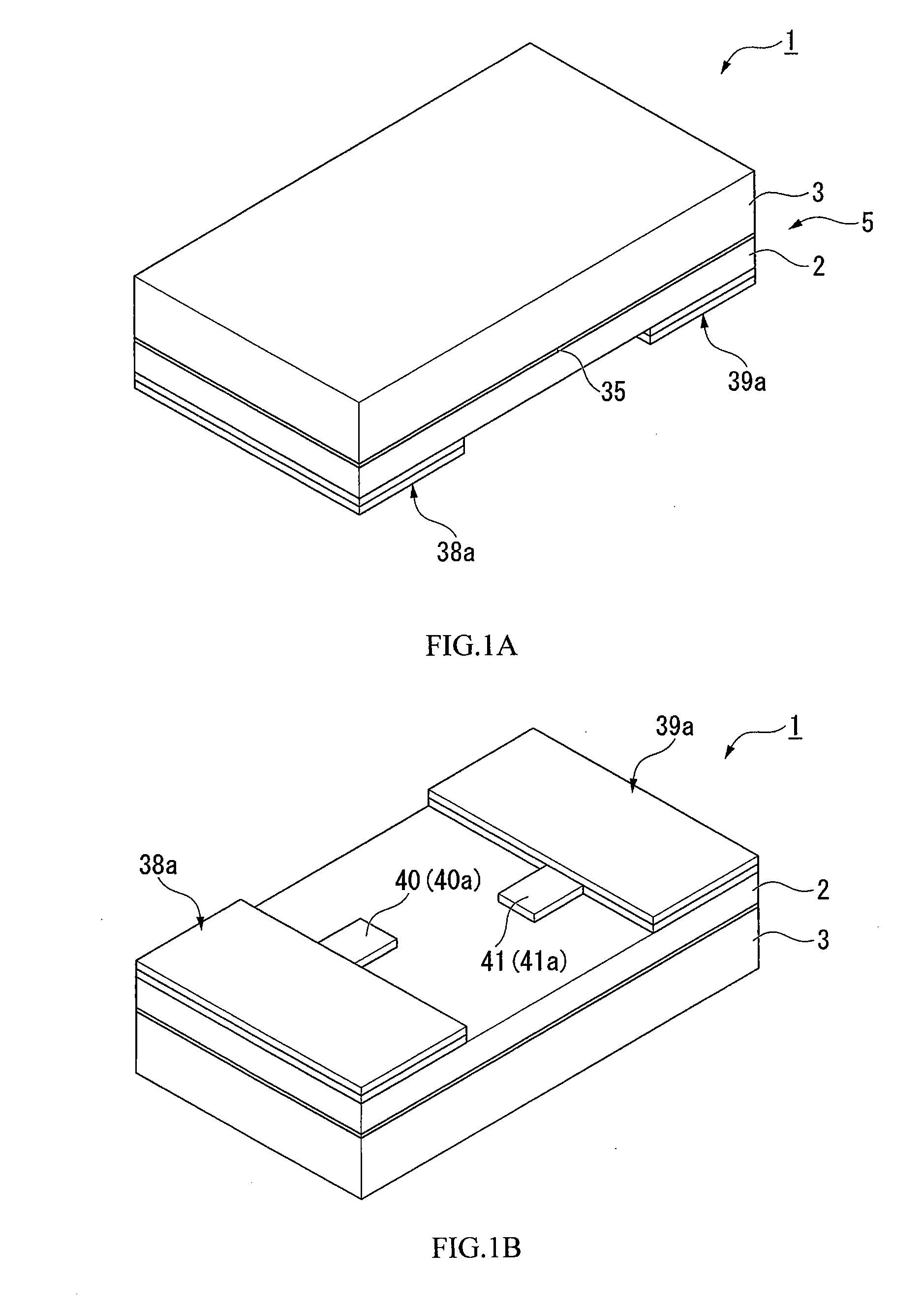
[0037]FIG. 1 is a perspective view showing a piezoelectric vibrator 1. As shown in FIG. 1(A), in the piezoelectric vibrator 1, a box-shaped package 5 is formed by being laminated with two layers, the two layers being a base substrate (a first substrate) 2 and a lid substrate (a second substrate) 3. The base substrate 2 and the lid substrate 3 are transparent insulating substrates made of a glass material such as soda lime glass, for example, and are formed in a board form having sizes with which the two substrates can be superimposed on each other. Further, a bonding film 35 is interposed between the base substrate 2 and the lid substrate 3 such that the base substrate 2 and the lid substrate 3 are bonded airtightly.

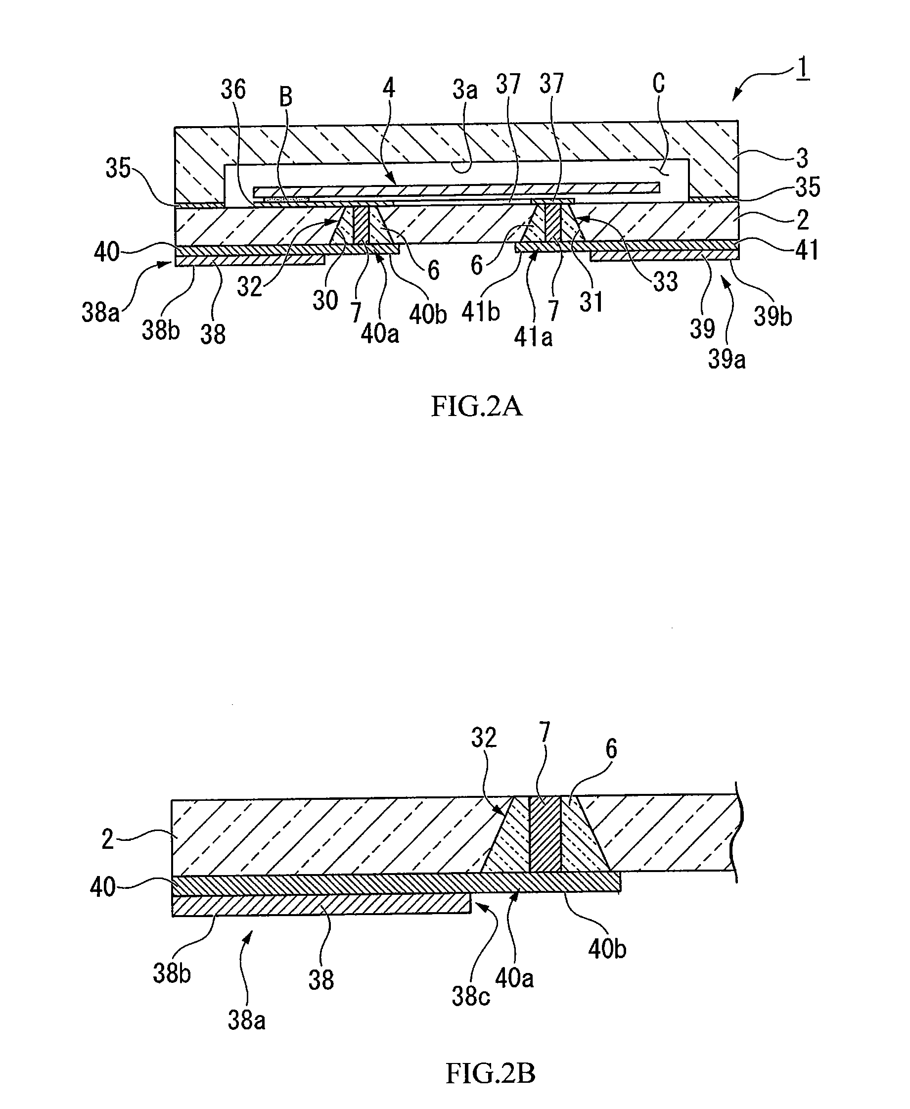
[0038]As shown in FIG. 1(A) and FIG. 1(B), two external electrode portions 38a, 38...

second embodiment

[0065]Next, a piezoelectric vibrator mounting body according to a second embodiment of the invention will be explained with reference to FIG. 5. Note that in respective embodiments described below, descriptions will be omitted for portions that have common structures with the above-described piezoelectric vibrator 1 and the piezoelectric vibrator mounting body 101 according to the first embodiment, while using the same reference numerals and signs as above therefor.

[0066]FIG. 5 is a side view showing a cross section of a part of a structure of a piezoelectric vibrator mounting body 201 according to the second embodiment. As shown in FIG. 5, the piezoelectric vibrator mounting body 201 does not have the two-layer structure having the first layer 40 and the second layer 38 as in the first embodiment, but it has a different structure from the first embodiment in that the piezoelectric vibrator mounting body 201 has an electrode layer 238 that integrally forms an external electrode port...

third embodiment

Piezoelectric Vibrator Manufacturing Method

[0071]Next, a piezoelectric vibrator manufacturing method of the invention will be explained with reference to FIG. 6. Note that descriptions will be omitted below for portions that have the same structures as those described above while using the same reference numerals and signs as above therefor.

[0072]FIG. 6 is a flowchart showing a manufacturing method of the piezoelectric vibrator 1 of the first embodiment. As shown in FIG. 6, the piezoelectric vibrator manufacturing method according to the embodiment is provided with a first process S1 in which the routing wiring portion and a bottom layer of the external electrode portion are formed by laminating a first layer containing a first metal on a glass substrate such as the base substrate 2, for example, and a second process S2 in which an upper layer of the external electrode portion is formed by laminating a second layer containing a second metal on a surface of the bottom layer of the ex...


PUM

PropertyMeasurementUnit
thicknessaaaaaaaaaa
affinityaaaaaaaaaa
areaaaaaaaaaaa

Abstract

This piezoelectric vibrator is provided with a package that is structured to include a first substrate and a second substrate that are bonded to each other such that a cavity is formed therebetween, an internal electrode portion that is formed on the first substrate and housed in the cavity, a piezoelectric vibrating reed that is sealed in the cavity and also is electrically connected to the internal electrode portion in the cavity, an external electrode portion that is formed on an external surface of the first substrate, a through electrode portion that is disposed so as not to be overlapped by the external electrode portion in a thickness direction of the first substrate, while one end of the through electrode portion is electrically connected to the internal electrode portion and another end of the through electrode portion is formed on the external surface of the first substrate while penetrating through the first substrate, and a routing wiring portion that electrically connects the through electrode portion and the external electrode portion.

Description

RELATED APPLICATIONS[0001]This application is a continuation of PCT / JP2009 / 053327 filed on Feb. 25, 2009. The entire content of this application is incorporated herein by reference.BACKGROUND OF THE INVENTION[0002]1. Field of the Invention[0003]The present invention relates to a piezoelectric vibrator, a piezoelectric vibrator mounting body and a piezoelectric vibrator manufacturing method.[0004]2. Description of the Related Art[0005]In recent years, mobile telephones and portable information terminal devices employ a piezoelectric vibrator that uses crystal or the like as a time source, a timing source of control signals or the like, and a reference signal source etc. Various examples of this type of piezoelectric vibrator are known. One known example is a surface mount device type piezoelectric vibrator. As this type of piezoelectric vibrator, a three-layer structure type is generally known in which a piezoelectric substrate that has a piezoelectric vibrating reed formed thereon i...

Claims


Application Information

Patent Timeline
Patent Type & Authority Applications(United States)
IPC IPC(8): H01L41/053H01L41/22
CPCY10T29/42H03H9/1021
Inventor SUGIYAMA, TAKESHI
Owner SII CRYSTAL TECH
Why Eureka
Try Eureka